LIGHTING LIGHTING SYSTEM(except LED Headlight) Turn Signal Light Circuit
DESCRIPTION
for LHD
The turn signal flasher relay turns on when it receives signals from the headlight dimmer switch integrated with the turn signal switch, causing the turn signal lights to flash.
for RHD
The combination meter assembly receives the turn signal switch information and controls the turn signal lights.
WIRING DIAGRAM
for LHD:
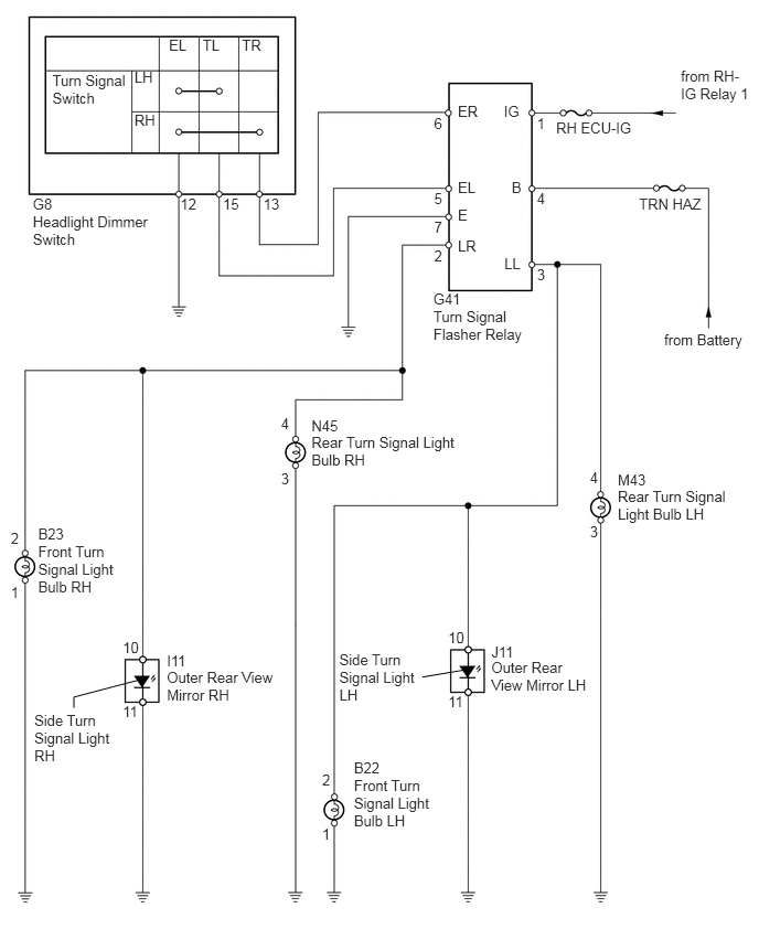
for RHD:
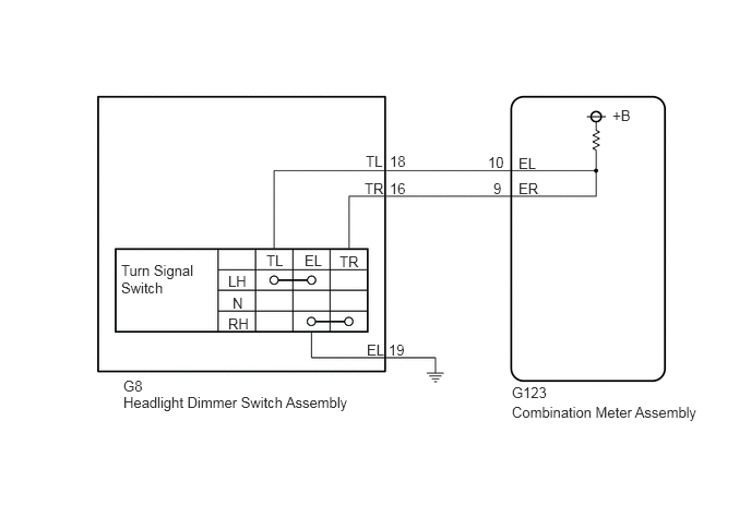
PROCEDURE
Choose the model to be inspected.
| Result | Proceed to |
|---|---|
| for LHD | A |
| for RHD | B |
A
B
When the headlight dimmer switch (turn signal light switch) is operated, check that the appropriate turn signal light flashes.
| Condition | Proceed to |
|---|---|
| All lights do not flash | A |
| LH turn signal lights do not flash | B |
| RH turn signal lights do not flash | C |
| Any one of turn signal lights does not flash | D |
A
B
C
D
Remove the RH ECU-IG fuse from the instrument panel junction block RH.
Remove the TRN HAZ fuse from the engine room No. 1 relay block.
Measure the resistance of the fuses.
- Standard Resistance:
Below 1 Ω
OK
NG
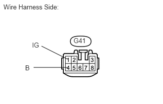
Disconnect the G41 turn signal flasher relay connector.
Measure the voltage of the wire harness side connector.
- Standard Voltage:
Tester Connection Condition Specified Condition G41-1 (IG) - Body ground Engine switch on (IG) 11 to 14 V G41-4 (B) - Body ground Always 11 to 14 V
OK
NG
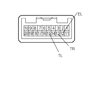
Remove the headlight dimmer switch.
Measure the resistance of the switch.
- Standard Resistance:
Tester Connection Condition Specified Condition 13 (TR) - 12 (EL) Right turn Below 1 Ω 15 (TL) - 12 (EL) Left turn Below 1 Ω 13 (TR) - 12 (EL) Neutral 10 kΩ or higher 15 (TL) - 12 (EL) Neutral 10 kΩ or higher
OK
NG
Disconnect the G8 headlight dimmer switch connector.
Disconnect the G41 turn signal flasher relay connector.
Measure the resistance of the wire harness side connectors.
- Standard Resistance:
Tester Connection Specified Condition G8-13 (TR) - G41-6 (ER) Below 1 Ω G8-13 (TR) or G41-6 (ER) - Body ground 10 kΩ or higher G8-15 (TL) - G41-5 (EL) Below 1 Ω G8-15 (TL) or - G41-5 (EL) - Body ground 10 kΩ or higher G8-12 (EL) - Body ground Below 1 Ω
OK
NG
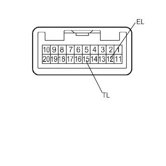
Remove the headlight dimmer switch.
Measure the resistance of the switch.
- Standard Resistance:
Tester Connection Condition Specified Condition 15 (TL) - 12 (EL) Left turn Below 1 Ω 15 (TL) - 12 (EL) Neutral 10 kΩ or higher
OK
NG
Disconnect the G8 headlight dimmer switch connector.
Disconnect the G41 turn signal flasher relay connector.
Measure the resistance of the wire harness side connectors.
- Standard Resistance:
Tester Connection Specified Condition G8-15 (TL) - G41-5 (EL) Below 1 Ω G8-15 (TL) or - G41-5 (EL) - Body ground 10 kΩ or higher G8-12 (EL) - Body ground Below 1 Ω
OK
NG
Disconnect the B22, J11 and M43 light connectors.
Disconnect the G41 turn signal flasher relay connector.
Measure the resistance of the wire harness side connectors.
- Standard Resistance:
Tester Connection Specified Condition B22-2 - G41-3 (LL) Below 1 Ω J11-10 - G41-3 (LL) Below 1 Ω M43-4 - G41-3 (LL) Below 1 Ω B22-2 or G41-3 (LL) - Body ground 10 kΩ or higher J11-10 or G41-3 (LL) - Body ground 10 kΩ or higher M43-4 or G41-3 (LL) - Body ground 10 kΩ or higher B22-1 - Body ground Below 1 Ω J11-11 - Body ground Below 1 Ω M43-3 - Body ground Below 1 Ω
OK
NG
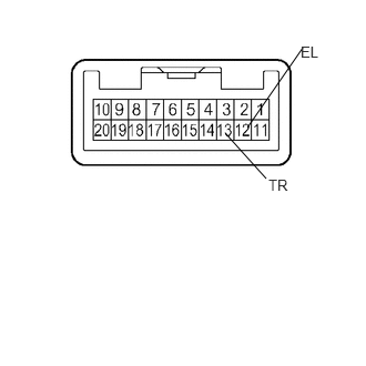
Remove the headlight dimmer switch.
Measure the resistance of the switch.
- Standard Resistance:
Tester Connection Condition Specified Condition 13 (TR) - 12 (EL) Right turn Below 1 Ω 13 (TR) - 12 (EL) Neutral 10 kΩ or higher
OK
NG
Disconnect the G8 headlight dimmer switch connector.
Disconnect the G41 turn signal flasher relay connector.
Measure the resistance of the wire harness side connectors.
- Standard Resistance:
Tester Connection Specified Condition G8-13 (TR) - G41-6 (ER) Below 1 Ω G8-13 (TR) or G41-6 (ER) - Body ground 10 kΩ or higher G8-12 (EL) - Body ground Below 1 Ω
OK
NG
Disconnect the B23, I11 and N45 light connectors.
Disconnect the G41 turn signal flasher relay connector.
Measure the resistance of the wire harness side connectors.
- Standard Resistance:
Tester Connection Specified Condition B23-2 - G41-2 (LR) Below 1 Ω I11-10 - G41-2 (LR) Below 1 Ω N45-4 - G41-2 (LR) Below 1 Ω B23-2 or G41-2 (LR) - Body ground 10 kΩ or higher I11-10 or G41-2 (LR) - Body ground 10 kΩ or higher N45-4 or G41-2 (LR) - Body ground 10 kΩ or higher B23-1 - Body ground Below 1 Ω I11-11 - Body ground Below 1 Ω N45-3 - Body ground Below 1 Ω
OK
NG
Check which light does not illuminate.
| result | Proceed to |
|---|---|
| Front turn signal light does not illuminate | A |
| Side turn signal light does not illuminate | B |
| Rear turn signal light does not illuminate | C |
A
B
C
Replace the front turn signal light bulb with a new one.
Check that the bulb illuminates normally.
- OK:
Bulb illuminates.
NG
OK
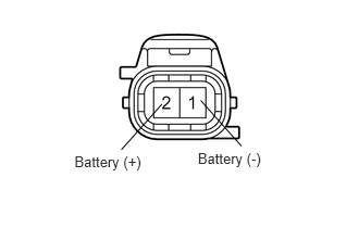
Remove the front turn signal light socket with bulb.
Connect the positive (+) lead from the battery to terminal 2 and the negative (-) lead to terminal 1. Then check that the bulb illuminates.
- OK:
Bulb illuminates.
OK
NG
for LH:
Disconnect the J11 mirror connector.
Disconnect the G41 relay connector.
Measure the resistance of the wire harness side connectors.
- Standard Resistance:
Tester Connection Specified Condition J11-10 - G41-3 (LL) Below 1 Ω J11-10 or G41-3 (LL) - Body ground 10 kΩ or higher J11-11 - Body ground 10 kΩ or higher
for RH:
Disconnect the I11 mirror connector.
Disconnect the G41 relay connector.
Measure the resistance of the wire harness side connectors.
- Standard Resistance:
Tester Connection Specified Condition I11-10 - G41-2 (LR) Below 1 Ω I11-10 or G41-2 (LR) - Body ground 10 kΩ or higher I11-11 - Body ground 10 kΩ or higher
OK
NG
Replace the rear turn signal light bulb with a new one.
Check that the bulb illuminates normally.
- OK:
Bulb illuminates.
NG
OK
Remove the rear combination light socket with bulb.
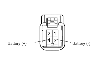
Connect the positive (+) lead from the battery to terminal 4 and the negative (-) lead to terminal 3. Then check that the bulb illuminates.
- OK:
Bulb illuminates.
OK
NG
(See pageVehicle Interior>LIGHTING>REAR COMBINATION LIGHT ASSEMBLY(except LED Headlight)>DISASSEMBLY)
Connect the GTS to the DLC3.
Turn the engine switch on (IG).
Turn the GTS on.
Enter the following menus: Body Electrical / Combination Meter (for RHD) / Data List.
Read the Data List according to the display on the GTS.
| Tester Display | Measurement Item/Range | Normal Condition | Diagnostic Note |
|---|---|---|---|
| Turn Signal Switch (Right) | Turn signal switch (Right) signal/ON or OFF | ON: Turn signal switch (Right) on
OFF: Turn signal switch (Right) off |
- |
| Turn Signal Switch (Left) | Turn signal switch (Left) signal/ON or OFF | ON: Turn signal switch (Left) on
OFF: Turn signal switch (Left) off |
- |
- OK:
Normal conditions listed above are displayed.
OK
NG
Remove the headlight dimmer switch assembly (See page Vehicle Interior>LIGHTING>HEADLIGHT DIMMER SWITCH>REMOVAL).
Inspect the headlight dimmer switch assembly (See page Vehicle Interior>LIGHTING>HEADLIGHT DIMMER SWITCH>INSPECTION).
OK
NG
Disconnect the G123 combination meter assembly connector.
Measure the resistance according to the value(s) in the table below.
- Standard Resistance:
Tester Connection Condition Specified Condition G8-16 (TR) - G123-9 (ER) Always Below 1 Ω G8-18 (TL) - G123-10 (EL) Always Below 1 Ω G8-19 (EL) - Body ground Always Below 1 Ω G8-16 (TR) or G123-9 (ER) - Body ground Always 10 kΩ or higher G8-18 (TL) or G123-10 (EL) - Body ground Always 10 kΩ or higher
OK
MG