Home › Vehicle Interior › LIGHTING › LIGHTING SYSTEM(except LED Headlight) › from 2016.05
RM24M0E _58 Vehicle Interior _059564 LIGHTING _0291933 LIGHTING SYSTEM(except LED Headlight) J

LIGHTING  LIGHTING SYSTEM(except LED Headlight)  Hazard Warning Switch Circuit  


DESCRIPTION

for LHD


When the hazard warning signal switch is turned on, the turn signal flasher relay turns on to flash the hazard warning signal lights.


for RHD


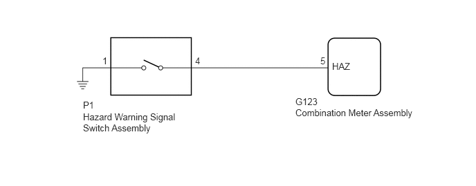
The combination meter assembly receives the hazard warning signal switch ON signal and controls the operation of the hazard warning lights.


WIRING DIAGRAM

for LHD:
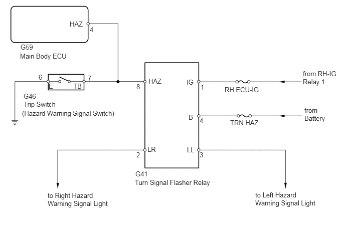

E132459E08
0.458,2.271 2.563,2.438 2.104,0.167 10 false (Hazard Warning Signal Switch) 0.49,2.083 1.313,2.323 0.823,0.24 10 false Trip Switch 0.49,1.917 0.958,2.125 0.469,0.208 10 false G46 2.813,3.531 3.208,3.698 0.396,0.167 10 false G41 1.823,1.542 2.198,1.719 0.375,0.177 10 false 7 0.802,1.521 1.052,1.698 0.25,0.177 10 false 6 1.01,1.708 1.125,1.885 0.115,0.177 10 false E 1.521,1.708 1.74,1.885 0.219,0.177 10 false TB 2.802,3.708 4.469,3.885 1.667,0.177 10 false Turn Signal Flasher Relay 3.917,2.354 4.052,2.51 0.135,0.156 10 false B 4.167,1.729 4.302,1.885 0.135,0.156 10 false 1 1.865,0.531 2,0.688 0.135,0.156 10 false 4 4.146,3.135 4.281,3.292 0.135,0.156 10 false 3 2.833,1.719 2.969,1.875 0.135,0.156 10 false 8 4.146,2.427 4.281,2.583 0.135,0.156 10 false 4 2.833,3.135 2.969,3.292 0.135,0.156 10 false 2 1.448,0.417 1.781,0.563 0.333,0.146 10 false HAZ 3.063,3.021 3.271,3.198 0.208,0.177 10 false LR 3.885,3.031 4.063,3.198 0.177,0.167 10 false LL 4.781,2.469 5.417,2.625 0.635,0.156 10 false TRN HAZ 0.99,3.979 2.417,4.49 1.427,0.51 10 false to Right Hazard Warning Signal Light 5.302,3.969 6.656,4.49 1.354,0.521 10 false to Left Hazard Warning Signal Light 4.667,1.781 5.438,1.938 0.771,0.156 10 false RH ECU-IG 6.292,1.448 6.958,1.979 0.667,0.531 10 false from RH-IG Relay 1 6.323,2.208 6.99,2.563 0.667,0.354 10 false from Battery 3.875,1.625 4.063,1.771 0.188,0.146 10 false IG 0.427,0.896 0.844,1.052 0.417,0.156 10 false G59 3.083,1.604 3.417,1.76 0.333,0.156 10 false HAZ 0.417,1.083 1.583,1.313 1.167,0.229 10 false Main Body ECU


for RHD:


E224262E22
1.542,0.833 1.635,0.979 0.094,0.146 10 false 1 2.938,0.833 3.031,0.979 0.094,0.146 10 false 4 4.823,0.833 4.917,0.979 0.094,0.146 10 false 5 5,0.917 5.292,1.063 0.292,0.146 10 false HAZ 4.448,1.448 5.167,1.823 0.719,0.375 10 false G123 4.448,1.615 6.281,1.76 1.833,0.146 10 false Combination Meter Assembly 1.25,1.5 1.521,1.646 0.271,0.146 10 false P1 1.25,1.677 2.958,2.083 1.708,0.406 10 false Hazard Warning Signal Switch Assembly


PROCEDURE

1.CONFIRM VEHICLE TYPE
a.

Choose the model to be inspected.

Result
Result Proceed to
for LHD A
for RHD B


A

2.CHECK DIMMER SWITCH OPERATION (TURN SIGNAL)

B

7.READ VALUE USING GTS
2.CHECK DIMMER SWITCH OPERATION (TURN SIGNAL)
a.

Operate the headlight dimmer switch (turn signal switch) to check that the turn signal light blinks normally.

OK:

Turn signal light blinks normally.


OK

3.PERFORM ACTIVE TEST USING GTS (HAZARD SIGNAL)

NG

3.PERFORM ACTIVE TEST USING GTS (HAZARD SIGNAL)
a.

Connect the GTS to the DLC3.


b.

Turn the engine switch on (IG).


c.

Turn the GTS on.


d.

Enter the following menus: Body Electrical / Main Body / Active Test.


e.

Perform the Active Test according to the display on the GTS.

Main Body
Item Test Details/Display (Range) Diagnostic Note
Hazard Hazard ON/OFF -

OK:

All hazard warning signal lights flash.


NG

4.CHECK WIRE HARNESS (MAIN BODY ECU - TURN SIGNAL FLASHER RELAY)

OK

6.INSPECT TRIP SWITCH (HAZARD WARNING SIGNAL SWITCH)
4.CHECK WIRE HARNESS (MAIN BODY ECU - TURN SIGNAL FLASHER RELAY)
a.

Disconnect the G59 ECU connector.


b.

Disconnect the G41 turn signal flasher relay connector.


c.

Measure the resistance of the wire harness side connectors.

Standard Resistance:
Tester Connection Specified Condition
G59-4 (HAZ) - G41-8 (HAZ) Below 1 Ω
G59-4 (HAZ) or G41-8 (HAZ) - Body ground 10 kΩ or higher


OK

5.CHECK OPERATION OF TURN SIGNAL FLASHER RELAY

NG

REPAIR OR REPLACE HARNESS OR CONNECTOR

5.CHECK OPERATION OF TURN SIGNAL FLASHER RELAY
a.

Replace the turn signal flasher relay with a normally functioning one or a new one.


b.

Check that the appropriate turn signal light flashes.

i.

Connect the GTS to the DLC3.


ii.

Turn the engine switch on (IG).


iii.

Turn the GTS on.


iv.

Enter the following menus: Body Electrical / Main Body / Active Test.


v.

Perform the Active Test according to the display on the GTS.

Main Body
Item Test Details/Display (Range) Diagnostic Note
Hazard Hazard ON/OFF -

OK:

All hazard warning signal lights flash.


OK

REPLACE TURN SIGNAL FLASHER RELAY

NG

REPLACE MAIN BODY ECU

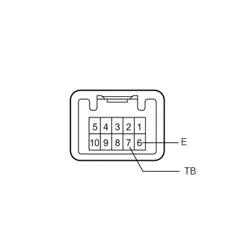
6.INSPECT TRIP SWITCH (HAZARD WARNING SIGNAL SWITCH)
E134348E03
2.647,1.993 2.901,2.153 0.254,0.161 10 E 2.694,2.417 3.047,2.578 0.352,0.161 10 TB 2.623,2.506 2.09,2.506 2.09,2.506 1.892,2.146 false 2.079,2.088 2.613,2.088 false

a.

Remove the trip switch.


b.

Measure the resistance of the switch.

Standard Resistance:
Tester Connection Condition Specified Condition
6 (E) - 7 (TB) OFF 10 kΩ or higher
6 (E) - 7 (TB) ON Below 23.4 Ω


OK

REPAIR OR REPLACE HARNESS OR CONNECTOR (TRIP SWITCH - TURN SIGNAL FLASHER RELAY AND BODY GROUND)

NG

REPLACE TRIP SWITCH

7.READ VALUE USING GTS
a.

Connect the GTS to the DLC3.


b.

Turn the engine switch on (IG).


c.

Turn the GTS on.


d.

Enter the following menus: Body Electrical / Combination Meter (for RHD) / Data List.


e.

Read the Data List according to the display on the tester..

Combination Meter (for RHD)
Tester Display Measurement Item/Range Normal Condition Diagnostic Note
Hazard Flasher Switch Hazard warning signal switch signal/ON or OFF ON: Hazard warning signal switch on
OFF: Hazard warning signal switch off
-

OK:

Normal conditions listed above are displayed.


OK

PROCEED TO NEXT SUSPECTED AREA SHOWN IN PROBLEM SYMPTOMS TABLE

NG

8.INSPECT HAZARD WARNING SIGNAL SWITCH ASSEMBLY
a.

Remove the hazard warning signal switch assembly (See page Vehicle Interior>LIGHTING>HAZARD WARNING SWITCH>REMOVAL).


b.

Inspect the hazard warning signal switch assembly (See page Vehicle Interior>LIGHTING>HAZARD WARNING SWITCH>INSPECTION).


OK

9.CHECK HARNESS AND CONNECTOR (HAZARD WARNING SIGNAL SWITCH - COMBINATION METER ASSEMBLY)

NG

REPLACE HAZARD WARNING SIGNAL SWITCH ASSEMBLY

9.CHECK HARNESS AND CONNECTOR (HAZARD WARNING SIGNAL SWITCH - COMBINATION METER ASSEMBLY)
a.

Disconnect the G123 combination meter assembly connector.


b.

Measure the resistance according to the value(s) in the table below.

Standard Resistance:
Tester Connection Condition Specified Condition
P1-4 - G123-5 (HAZ) Always Below 1 Ω
P1-4 or G123-5 (HAZ) - Body ground Always 10 kΩ or higher
P1-1 - Body ground Always Below 1 Ω


OK

REPLACE COMBINATION METER ASSEMBLY

NG

REPAIR OR REPLACE HARNESS OR CONNECTOR