DOOR LOCK WIRELESS DOOR LOCK CONTROL SYSTEM No Answer-Back
DESCRIPTION
In some cases, wireless door lock control functions are normal but the hazard warning lights and/or wireless door lock buzzer answer-back function(s) does not operate. In such cases, the certification ECU's hazard warning lights and wireless door lock buzzer signal outputs may be malfunctioning.
- NOTICE:
-
The wireless door lock control system uses the CAN communication system. Inspect the communication function by following How to Proceed with Troubleshooting. Troubleshoot the wireless door lock control system after confirming that the communication system is functioning properly. (See pageVehicle Interior>DOOR LOCK>WIRELESS DOOR LOCK CONTROL SYSTEM>HOW TO PROCEED WITH TROUBLESHOOTING)
WIRING DIAGRAM
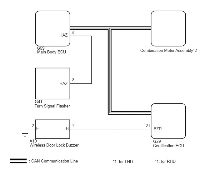
PROCEDURE
Connect the GTS to the DLC3.
Turn the engine switch on (IG).
Turn the GTS on.
Enter the following menus: Customize Setting / Wireless Door Lock.
Select the setting by referring to the table below.
| Display (Item) | Default | Contents | Setting |
|---|---|---|---|
| Hazard Answer Back | ON | When wireless lock switch on transmitter pressed, all hazard warning lights illuminate once. When unlock switch pressed, all hazard warning lights illuminate twice | ON / OFF |
| Wireless Buzzer Resp* | ON | ON / OFF of wireless buzzer response function | ON / OFF |
*: w/ Wireless Door Lock Buzzer Answer-back Function
- Result:
Result Proceed to Items are ON A An item is OFF B
A
B
Check the wireless door lock control function using the electrical key transmitter
- Result:
Result Proceed to Wireless door lock/unlock operates properly. A Wireless door lock/unlock does not operate properly. B
A
B
Enter the following menus: Body Electrical / Main Body / Data List.
Read the Data List according to the display on the GTS.
| Tester Display | Measurement Item/Range | Normal Condition | Diagnostic Note |
|---|---|---|---|
| D-Door Lock Pos SW | Driver side door lock position switch signal / ON or OFF | ON: Driver side door is unlocked
OFF: Driver side door is locked |
- |
| P-Door Lock Pos SW | Passenger side door lock position switch signal / ON or OFF | ON: Passenger side door is unlocked
OFF: Passenger side door is locked |
- |
| RR-Door Lock Pos SW | Slide door RH lock position switch signal / ON or OFF | ON: Slide door RH is unlocked
OFF: Slide door RH is locked |
- |
| RL-Door Lock Pos SW | Slide door LH lock position switch signal / ON or OFF | ON: Slide door LH is unlocked
OFF: Slide door LH is locked |
- |
- OK:
The GTS display changes correctly in response to the lock/unlock operation.
OK
NG
Check the wireless door lock control functions by operating the transmitter switch.
- Result:
Result Proceed to Wireless door lock functions are normal but hazard warning lights answer-back does not occur (for LHD) A Wireless door lock functions are normal but hazard warning lights answer-back does not occur (for RHD) B Wireless door lock functions are normal but wireless door lock buzzer answer-back does not occur C Doors cannot be locked and unlocked with electrical key transmitter D
A
B
C
D
Check that the hazard warning lights flash continuously when the hazard warning signal switch is pressed.
- OK:
Hazard warning lights flash continuously.
OK
NG
(See pageVehicle Interior>DOOR LOCK>WIRELESS DOOR LOCK CONTROL SYSTEM>HOW TO PROCEED WITH TROUBLESHOOTING)
Enter the following menus: Customize Setting / Wireless Door Lock.
Select the setting by referring to the table below.
| Tester Display | Test Part | Control Range |
|---|---|---|
| Hazard | Turn signal flasher relay ON / OFF | - |
- OK:
Hazard warning lights are turned ON / OFF.
NG
OK
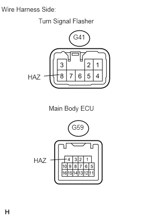
Disconnect the G59 and G41 connectors.
Measure the resistance of the wire harness side connectors.
- Standard resistance:
Tester Connection Specified Condition G59-4 (HAZ) - G41-8 (HAZ) Below 1 Ω G59-4 (HAZ) - Body ground 10 kΩ or higher G41-8 (HAZ) - Body ground 10 kΩ or higher
OK
NG
Enter the following menus: Customize Setting / Wireless Door Lock.
Select the setting by referring to the table below.
| Tester Display | Test Part | Control Range |
|---|---|---|
| Wireless Buzzer | Operate wireless door lock buzzer ON / OFF | - |
- OK:
Hazard warning lights are turned ON / OFF.
NG
OK
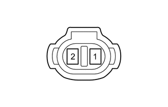
Measure the resistance between terminals 1(E) and 2(B) of the buzzer.
- OK:
Approximately 1 kΩ.
OK
NG
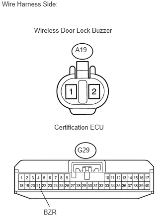
Disconnect the A19 connector.
Disconnect the G29 connector.
Measure the resistance of the wire harness side connectors.
- Standard resistance:
Tester Connection Specified Condition A19-1(B) - G29-21 (BZR) Below 1 Ω A19-2(E) - Body ground Below 1 Ω A19-1(B) - Body ground 10 kΩ or higher G29-21(BZR) - Body ground 10 kΩ or higher
OK
NG
Check that the hazard warning lights blink when the hazard warning signal switch is pressed.
- OK:
Hazard warning lights blink.
OK
NG
(See pageVehicle Interior>LIGHTING>LIGHTING SYSTEM(for LED Headlight)>Hazard Warning Switch Circuit)