U241E AUTOMATIC TRANSMISSION / TRANSAXLE SHIFT LEVER(for RHD) REMOVAL
PROCEDURE

 1.DISCONNECT CABLE FROM NEGATIVE BATTERY TERMINAL
- NOTICE:
-
Wait at least 90 seconds after disconnecting the cable from the negative (-) battery terminal to prevent airbag and seat belt pretensioner activation (See page General>INTRODUCTION>REPAIR INSTRUCTION>PRECAUTION).
33554H
2.REMOVE SHIFT LOCK RELEASE BUTTON COVER
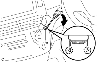
Using a screwdriver with its tip wrapped with protective tape, disengage the 2 claws to remove the shift lock release button cover from the heater control and accessory assembly.
| *a | Protective Tape |
33504F
3.REMOVE SHIFT LEVER KNOB SUB-ASSEMBLY
Move the shift lever to N.
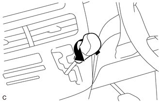
Turn the shift lever knob sub-assembly counterclockwise and remove it.
4.REMOVE CENTER INSTRUMENT CLUSTER FINISH PANEL ASSEMBLY
55041B
5.REMOVE NO. 1 INSTRUMENT PANEL BOX DOOR SUB-ASSEMBLY
55042B
6.REMOVE NO. 2 INSTRUMENT PANEL BOX DOOR SUB-ASSEMBLY
55550
7.REMOVE GLOVE COMPARTMENT DOOR ASSEMBLY
55607
8.REMOVE NO. 2 INSTRUMENT PANEL UNDER COVER SUB-ASSEMBLY
67913B
9.REMOVE FRONT DOOR SCUFF PLATE RH
62111C
10.REMOVE COWL SIDE TRIM BOARD RH
55606
11.REMOVE NO. 1 INSTRUMENT PANEL UNDER COVER SUB-ASSEMBLY
55432B
12.REMOVE INSTRUMENT PANEL FINISH PANEL LOWER
58534E
13.REMOVE FLOOR CARPET COVER CENTER LH
58533C
14.REMOVE FLOOR CARPET COVER CENTER RH
55434B
15.REMOVE INSTRUMENT PANEL FINISH PANEL LOWER CENTER
55475B
16.REMOVE CENTER INSTRUMENT CLUSTER FINISH PANEL GARNISH
33820B
17.DISCONNECT TRANSMISSION CONTROL CABLE ASSEMBLY
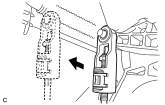
Disconnect the transmission control cable assembly from the shift lever assembly.
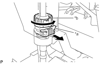
Using a screwdriver, pull out the stopper of the transmission control cable assembly.
- NOTICE:
-
Do not remove the stopper. If the stopper is removed, reinstall it to its original position.
| *a | Stopper |
| *b | Nut |
Rotate the nut counterclockwise approximately 180°, and while holding the nut in that position, disconnect the transmission control cable assembly from the shift lever assembly.
- NOTICE:
-
Do not over-rotate the nut as it will come off the interior spring and the transmission control cable assembly will not be reusable.
18.REMOVE SHIFT LEVER ASSEMBLY
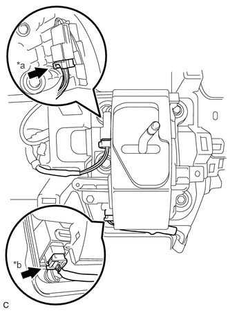
Disconnect the transmission control switch connector.
| *a | Transmission Control Switch Connector |
| *b | Shift Lock Control ECU Sub-assembly Connector |
Disconnect the shift lock control ECU sub-assembly connector.
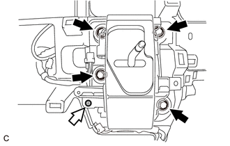
Remove the 4 bolts, screw and shift lever assembly.

|
Bolt |

|
Screw |