INTERIOR PANEL LOWER INSTRUMENT PANEL REMOVAL
PROCEDURE

 1. TABLE OF BOLT, SCREW AND NUT
- HINT:
-
All bolts, screws and nuts relevant to installing and removing the instrument panel are shown along with their alphabet codes in the table below.
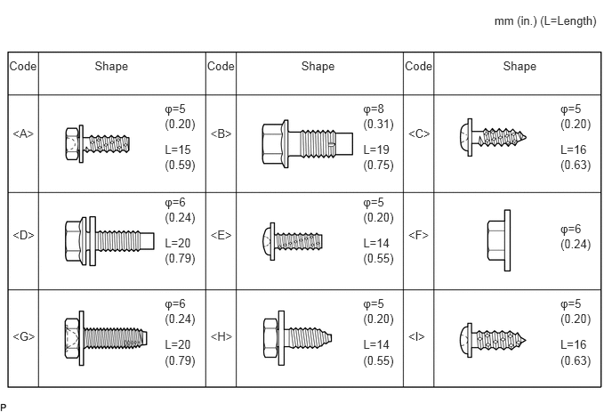 0.106,0.684 0.581,0.895 0.474,0.211 10 Code 2.423,0.684 2.897,0.895 0.474,0.211 10 Code 4.739,0.684 5.213,0.895 0.474,0.211 10 Code 0.148,1.484 0.623,1.695 0.474,0.211 10 <A> 2.465,1.484 2.939,1.695 0.474,0.211 10 <B> 4.781,1.484 5.255,1.695 0.474,0.211 10 <C> 0.148,2.67 0.623,2.882 0.474,0.211 10 <D> 2.465,2.67 2.939,2.882 0.474,0.211 10 <E> 4.781,2.67 5.255,2.882 0.474,0.211 10 <F> 0.148,3.856 0.623,4.068 0.474,0.211 10 <G> 2.465,3.856 2.939,4.068 0.474,0.211 10 <H> 4.781,3.856 5.255,4.068 0.474,0.211 10 <I> 1.109,0.683 1.556,0.969 0.447,0.285 10 Shape 3.528,0.683 3.975,0.969 0.447,0.285 10 Shape 5.891,0.683 6.338,0.969 0.447,0.285 10 Shape 5.79,0.156 7.049,0.459 1.259,0.304 10 mm (in.) (L=Length) 1.93,1.188 2.377,1.395 0.447,0.206 10 φ=5 1.93,1.364 2.414,1.571 0.483,0.206 10 (0.20) 1.93,1.666 2.422,1.873 0.491,0.206 10 L=15 1.93,1.846 2.416,2.052 0.486,0.206 10 (0.59) 4.254,1.188 4.701,1.395 0.447,0.206 10 φ=8 4.254,1.364 4.737,1.571 0.483,0.206 10 (0.31) 4.254,1.666 4.745,1.873 0.491,0.206 10 L=19 4.254,1.846 4.740,2.052 0.486,0.206 10 (0.75) 6.563,1.188 7.010,1.395 0.447,0.206 10 φ=5 6.563,1.364 7.046,1.571 0.483,0.206 10 (0.20) 6.563,1.666 7.054,1.873 0.491,0.206 10 L=16 6.563,1.846 7.049,2.052 0.486,0.206 10 (0.63) 1.93,2.282 2.377,2.488 0.447,0.206 10 φ=6 1.93,2.458 2.414,2.664 0.483,0.206 10 (0.24) 1.93,2.76 2.422,2.966 0.491,0.206 10 L=20 1.93,2.939 2.416,3.146 0.486,0.206 10 (0.79) 4.254,2.282 4.701,2.488 0.447,0.206 10 φ=5 4.254,2.458 4.737,2.664 0.483,0.206 10 (0.20) 4.254,2.76 4.745,2.966 0.491,0.206 10 L=14 4.254,2.939 4.740,3.146 0.486,0.206 10 (0.55) 6.563,2.59 7.010,2.797 0.447,0.206 10 φ=6 6.563,2.766 7.046,2.973 0.483,0.206 10 (0.24) 1.93,3.474 2.377,3.680 0.447,0.206 10 φ=6 1.93,3.649 2.414,3.856 0.483,0.206 10 (0.24) 1.93,3.951 2.422,4.158 0.491,0.206 10 L=20 1.93,4.131 2.416,4.337 0.486,0.206 10 (0.79) 4.254,3.474 4.701,3.680 0.447,0.206 10 φ=5 4.254,3.649 4.737,3.856 0.483,0.206 10 (0.20) 4.254,3.951 4.745,4.158 0.491,0.206 10 L=14 4.254,4.131 4.740,4.337 0.486,0.206 10 (0.55) 6.563,3.474 7.010,3.680 0.447,0.206 10 φ=5 6.563,3.649 7.046,3.856 0.483,0.206 10 (0.20) 6.563,3.951 7.054,4.158 0.491,0.206 10 L=16 6.563,4.131 7.049,4.337 0.486,0.206 10 (0.63)
28800
2.DISCONNECT CABLE FROM NEGATIVE BATTERY TERMINAL
- CAUTION:
-
Wait at least 90 seconds after disconnecting the cable from the negative (-) battery terminal to prevent airbag and seat belt pretensioner activation.
55302A
3.REMOVE UPPER INSTRUMENT PANEL SUB-ASSEMBLY
33504F
4.REMOVE SHIFT LEVER KNOB SUB-ASSEMBLY (for LHD)
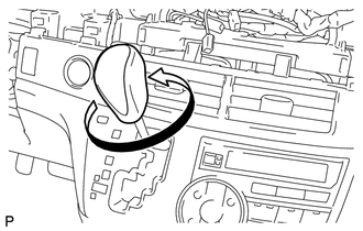
Turn the shift lever knob sub-assembly counterclockwise and remove the shift lever knob sub-assembly.
67914B
5.REMOVE FRONT DOOR SCUFF PLATE LH
67913B
6.REMOVE FRONT DOOR SCUFF PLATE RH
- HINT:
-
Use the same procedures described for the LH side.
62112
7.REMOVE COWL SIDE TRIM BOARD LH
62111C
8.REMOVE COWL SIDE TRIM BOARD RH
- HINT:
-
Use the same procedures described for the LH side.
55607
9.REMOVE NO. 2 INSTRUMENT PANEL UNDER COVER SUB-ASSEMBLY
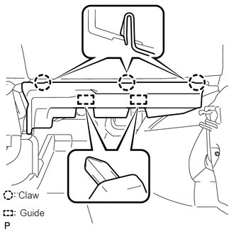
Disengage the 3 claws and 2 guides, and remove the No. 2 instrument panel under cover sub-assembly.
89340A
10.REMOVE CLEARANCE WARNING ECU ASSEMBLY (w/ Clearance Sonar)
55474B
11.REMOVE INSTRUMENT CLUSTER FINISH PANEL GARNISH (for LHD)
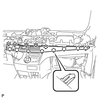
Disengage the 13 claws.
Disconnect the connector and remove the instrument cluster finish panel garnish.
55446A
12.REMOVE NO. 1 SWITCH HOLE BASE
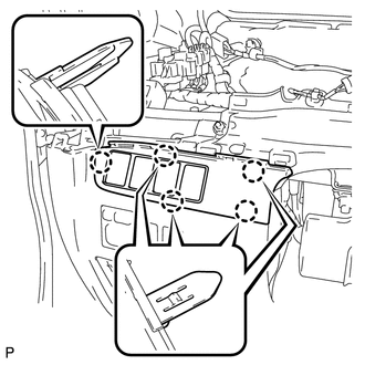
Disengage the 5 claws.
Disconnect each connector and remove the No. 1 switch hole base.
55606
13.REMOVE NO. 1 INSTRUMENT PANEL UNDER COVER SUB-ASSEMBLY
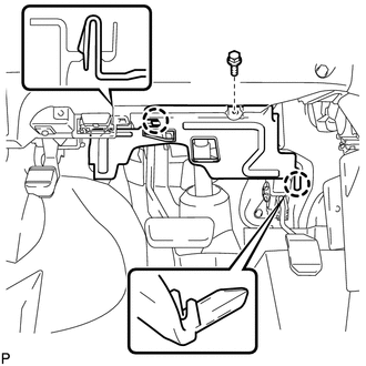
Remove the screw.
Disengage the 2 claws and remove the No. 1 instrument panel under cover sub- assembly.
55432B
14.REMOVE INSTRUMENT PANEL FINISH PANEL LOWER (w/o Knee Airbag)
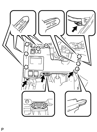
Remove the 3 screws and disengage the 8 claws.
Disconnect the hood lock control lever cable and fuel lid open lever cable.
Remove the duct from the room temperature sensor.
Disconnect each connector and remove the instrument panel finish panel lower.
55432B
15.REMOVE INSTRUMENT PANEL FINISH PANEL LOWER (w/ Knee Airbag)
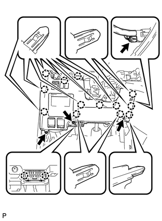
Remove the 3 screws and disengage the 13 claws.
Disconnect the hood lock control lever cable and fuel lid open lever cable.
Remove the duct from the room temperature sensor.
Disconnect each connector and remove the instrument panel finish panel lower.
58534E
16.REMOVE FLOOR CARPET COVER CENTER LH
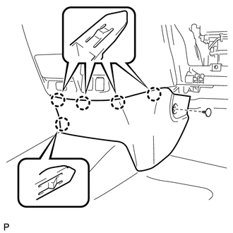
Disengage the clip.
Disengage the 5 claws and remove the floor carpet cover center LH.
58533C
17.REMOVE FLOOR CARPET COVER CENTER RH
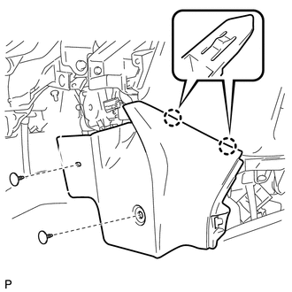
Disengage the 2 clips.
Disengage the 2 claws and remove the floor carpet cover center RH.
55434B
18.REMOVE INSTRUMENT PANEL FINISH PANEL LOWER CENTER
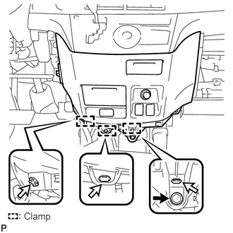
Remove the bolt.
Disengage the 3 clamps.
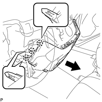
Disengage the 3 claws as shown in the illustration.
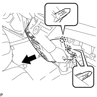
Disengage the 3 claws as shown in the illustration.
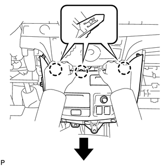
Disengage the 3 claws and remove the instrument panel finish panel lower center as shown in the illustration.
55433B
19.REMOVE NO. 2 INSTRUMENT PANEL FINISH PANEL LOWER (for LHD)
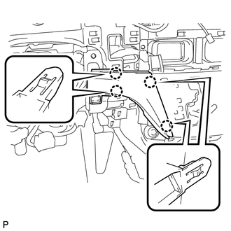
Disengage the 4 claws and remove the No. 2 instrument panel finish panel lower.
55900A
20.REMOVE HEATER CONTROL AND ACCESSORY (for LHD)
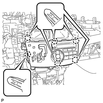
Disengage the 6 claws.
Disconnect each connector and remove the heater control and accessory.
55475B
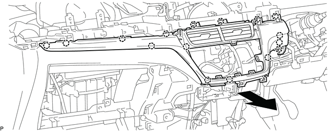
21.REMOVE CENTER INSTRUMENT CLUSTER FINISH PANEL GARNISH (for RHD)
Disengage the 16 claws and remove the center instrument cluster finish panel garnish as shown in the illustration.
33820B
22.DISCONNECT TRANSMISSION CONTROL CABLE ASSEMBLY
for LHD with U241E (See page Drivetrain>U241E (AUTOMATIC TRANSMISSION / TRANSAXLE)>SHIFT LEVER(for LHD)>REMOVAL)
for RHD with U241E (See page Drivetrain>U241E (AUTOMATIC TRANSMISSION / TRANSAXLE)>SHIFT LEVER(for RHD)>REMOVAL)
for LHD with U660E (See page Drivetrain>U660E (AUTOMATIC TRANSMISSION / TRANSAXLE)>SHIFT LEVER(for LHD)>REMOVAL)
for RHD with U660E (See page Drivetrain>U660E (AUTOMATIC TRANSMISSION / TRANSAXLE)>SHIFT LEVER(for RHD)>REMOVAL)
for LHD with K112 (See page Drivetrain>K112 (CVT)>SHIFT LEVER(for LHD)>REMOVAL)
for RHD with K112 (See page Drivetrain>K112 (CVT)>SHIFT LEVER(for RHD)>REMOVAL)
33560
23.REMOVE SHIFT LOCK CONTROL UNIT ASSEMBLY
for LHD with U241E (See page Drivetrain>U241E (AUTOMATIC TRANSMISSION / TRANSAXLE)>SHIFT LEVER(for LHD)>REMOVAL)
for RHD with U241E (See page Drivetrain>U241E (AUTOMATIC TRANSMISSION / TRANSAXLE)>SHIFT LEVER(for RHD)>REMOVAL)
for LHD with U660E (See page Drivetrain>U660E (AUTOMATIC TRANSMISSION / TRANSAXLE)>SHIFT LEVER(for LHD)>REMOVAL)
for RHD with U660E (See page Drivetrain>U660E (AUTOMATIC TRANSMISSION / TRANSAXLE)>SHIFT LEVER(for RHD)>REMOVAL)
for LHD with K112 (See page Drivetrain>K112 (CVT)>SHIFT LEVER(for LHD)>REMOVAL)
for RHD with K112 (See page Drivetrain>K112 (CVT)>SHIFT LEVER(for RHD)>REMOVAL)
55400
24.REMOVE INSTRUMENT PANEL SAFETY PAD ASSEMBLY (w/o Knee Airbag)
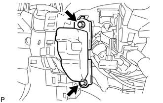
Remove the 2 bolts and instrument panel safety pad assembly.
55401E
25.REMOVE INSTRUMENT PANEL SAFETY PAD SUB-ASSEMBLY (w/o Knee Airbag)
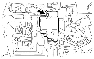
Remove the bolt and instrument panel safety pad sub-assembly.
73900
26.REMOVE DRIVER SIDE KNEE AIRBAG ASSEMBLY (w/ Knee Airbag)
83100
27.REMOVE COMBINATION METER ASSEMBLY
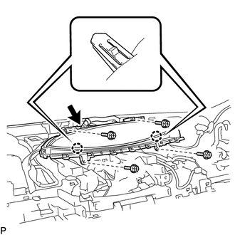
Disconnect the connector.
Remove the 4 screws.
Disengage the 2 claws to remove the combination meter assembly.
86860
28.REMOVE NAVIGATION ANTENNA ASSEMBLY (w/ Navigation System)
55312
29.REMOVE INSTRUMENT PANEL LOWER
Disconnect each connector and each clamp.
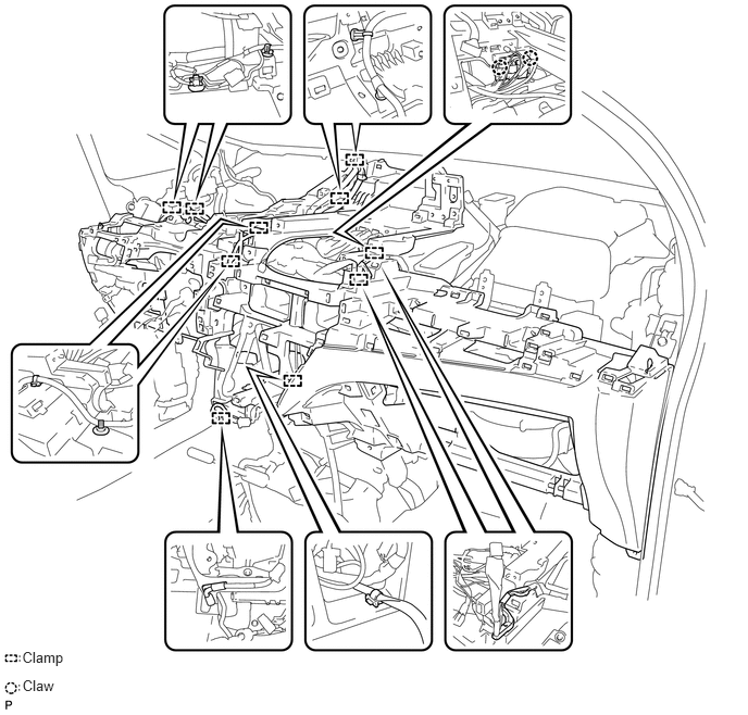
Remove the 3 bolts, 11 screws and 4 nuts.
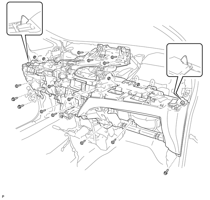
Disengage the 2 claws and remove the instrument panel lower.