BRAKE CONTROL / DYNAMIC CONTROL SYSTEMS ANTI-LOCK BRAKE SYSTEM C0278/11 Open in ABS Solenoid Relay Circuit
DESCRIPTION
The solenoid relay supplies power to the ABS solenoid.
After the engine switch is turned on (IG), the vehicle speed has reached 15 km/h (9 mph) and the solenoid is determined to be normal by the initial check self-diagnosis, the relay switches on. If open circuit is detected, the relay switches off.
These DTCs may be set if the voltage supply to the solenoid relay (+BS) falls below the DTC detection threshold due to the battery or alternator outputs being insufficient.
| DTC No. | DTC Detection Condition | Trouble Area |
|---|---|---|
| C0278/11 | When either condition below is met:
1.
Internal circuit malfunction in ECU. 2.
Valve relay voltage is 0.8 x IG or less for 0.5 sec. 3.
Valve relay voltage is high level relay OFF. |
·
ABS NO. 2 fuse ·
Wire harness (+BS circuit) ·
Brake actuator |
- HINT:
-
C0278/11: The skid control ECU begins to detect these DTCs when the vehicle speed exceeds 15 km/h (9 mph).
WIRING DIAGRAM
Refer to DTC C0226/21, C0236/22, C0246/23, C0256/24 (see page Brake>BRAKE CONTROL / DYNAMIC CONTROL SYSTEMS>ANTI-LOCK BRAKE SYSTEM>C0226/21).
PROCEDURE
Remove the ABS NO. 2 fuse from the engine room No. 1 relay block.
Measure the resistance of the fuse.
- Standard resistance:
Below 1 Ω
OK
NG
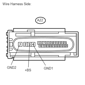
Disconnect the A22 ECU connector.
Measure the voltage of the wire harness side connector.
- Standard voltage:
Tester Connection Specified Condition A22-3 (+BS) - Body ground 10 to 14 V
Measure the resistance of the wire harness side connector.
- Standard resistance:
Tester Connection Specified Condition A22-4 (GND1) - Body ground Below 1 Ω A22-1 (GND2) - Body ground Below 1 Ω
OK
NG
Clear the DTCs (see page Brake>BRAKE CONTROL / DYNAMIC CONTROL SYSTEMS>ANTI-LOCK BRAKE SYSTEM>DTC CHECK / CLEAR).
Start the engine.
Drive the vehicle at 15 km/h (9 mph) or more to activate the initial check.
Check if the same DTC(s) is output (see page Brake>BRAKE CONTROL / DYNAMIC CONTROL SYSTEMS>ANTI-LOCK BRAKE SYSTEM>DTC CHECK / CLEAR).
| Result | Proceed to |
|---|---|
| DTC is not output | A |
| DTC is output | B |
A
B
(See pageBrake>BRAKE CONTROL / DYNAMIC CONTROL SYSTEMS>BRAKE ACTUATOR(for 2AZ-FE without VSC)>REMOVAL)