RM24M0E
_54
Brake
_059583
BRAKE CONTROL / DYNAMIC CONTROL SYSTEMS
_0292158
VEHICLE STABILITY CONTROL SYSTEM
J
BRAKE CONTROL / DYNAMIC CONTROL SYSTEMS VEHICLE STABILITY CONTROL SYSTEM TC and CG Terminal Circuit
DESCRIPTION
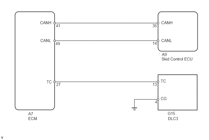
Connecting terminals TC and CG of the DLC3 causes the skid control ECU to display 2-digit DTCs by flashing the ABS warning light.
WIRING DIAGRAM
5.552,1.792 6.719,2.135
1.167,0.344
10
false
A9
5.531,0.698 6.104,0.885
0.573,0.188
10
false
CANH
5.531,1.313 6.104,1.5
0.573,0.188
10
false
CANL
1.375,0.698 1.948,0.885
0.573,0.188
10
false
CANH
1.385,1.313 1.958,1.5
0.573,0.188
10
false
CANL
0.969,3.833 1.396,4.188
0.427,0.354
10
false
A7
5.51,3.313 5.833,3.51
0.323,0.198
10
false
CG
5.51,2.708 5.792,2.906
0.281,0.198
10
false
TC
1.594,2.74 1.875,2.938
0.281,0.198
10
false
TC
5.75,3.823 6.24,4.146
0.49,0.323
10
false
G15
5.313,3.427 5.458,3.615
0.146,0.188
10
false
4
5.229,2.823 5.417,3.01
0.188,0.188
10
false
13
5.229,1.406 5.417,1.594
0.188,0.188
10
false
14
5.229,0.802 5.417,0.99
0.188,0.188
10
false
35
1.917,0.802 2.094,0.979
0.177,0.177
10
false
41
1.906,1.417 2.083,1.594
0.177,0.177
10
false
49
1.927,2.823 2.156,3.01
0.229,0.188
10
false
27
5.542,1.948 6.708,2.292
1.167,0.344
10
false
Skid Control ECU
5.76,4 6.25,4.323
0.49,0.323
10
false
DLC3
0.969,4 1.396,4.354
0.427,0.354
10
false
ECM
PROCEDURE
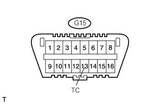
1.CHECK DLC3 (TC VOLTAGE)
a.
1.771,1.417 1.594,1.792
false
1.552,0.396 1.833,0.573
0.281,0.177
10
false
G15
1.49,1.813 1.75,2.01
0.26,0.198
10
false
TC
Turn the engine switch on (IG).
b.
Measure the voltage of the DLC3.
- Standard voltage:
Tester Connection Specified Condition G15-13 (TC) - Body ground 10 to 14 V
OK
2.CHECK CAN COMMUNICATION SYSTEM
NG
3.CHECK WIRE HARNESS (DLC3 - ECM)
2.CHECK CAN COMMUNICATION SYSTEM
a.
Check the DTC (see page Brake>BRAKE CONTROL / DYNAMIC CONTROL SYSTEMS>VEHICLE STABILITY CONTROL SYSTEM>DTC CHECK / CLEAR).
| Result | Proceed to |
|---|---|
| DTC is not output (for 2AZ-FE) | A |
| DTC is not output (for 2GR-FE) | B |
| DTC is output | C |
A
REPLACE ABS AND TRACTION ACTUATOR ASSEMBLY
B
REPLACE ABS AND TRACTION ACTUATOR ASSEMBLY
C
REPAIR CIRCUIT INDICATED BY OUTPUT DTC
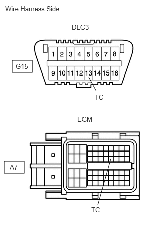
3.CHECK WIRE HARNESS (DLC3 - ECM)
0.25,1.25 0.667,1.5
0.417,0.25
0.083,3.333 0.5,3.583
0.417,0.25
1.99,1.885 1.833,1.594
false
2.021,4.24 2.292,3.281
false
0.104,0.094 1.51,0.344
1.406,0.25
10
false
Wire Harness Side:
0.323,1.292 0.938,1.531
0.615,0.24
10
false
G15
1.49,0.479 2.104,0.719
0.615,0.24
10
false
DLC3
1.958,1.927 2.573,2.167
0.615,0.24
10
false
TC
1.604,2.385 2.219,2.625
0.615,0.24
10
false
ECM
0.198,3.375 0.813,3.615
0.615,0.24
10
false
A7
1.885,4.26 2.5,4.5
0.615,0.24
10
false
TC
a.
Turn the engine switch off.
b.
Disconnect the A7 ECM connector.
c.
Measure the resistance of the wire harness side connectors.
- Standard resistance:
Tester Connection Specified Condition G15-13 (TC) - A7-27 (TC) Below 1 Ω A7-27 (TC) - Body ground 10 kΩ or higher
OK
4.CHECK WIRE HARNESS (DLC3 - BODY GROUND)
NG
REPAIR OR REPLACE HARNESS OR CONNECTOR
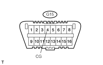
4.CHECK WIRE HARNESS (DLC3 - BODY GROUND)
a.
1.563,1.052 1.354,1.781
false
1.542,0.396 1.823,0.573
0.281,0.177
10
false
G15
1.188,1.813 1.469,1.948
0.281,0.135
10
false
CG
Measure the resistance of the DLC3.
- Standard resistance:
Tester Connection Specified Condition G15-4 (CG) - Body ground Below 1 Ω
OK
5.CHECK CAN COMMUNICATION SYSTEM
NG
REPAIR OR REPLACE HARNESS OR CONNECTOR
5.CHECK CAN COMMUNICATION SYSTEM
a.
Check if the CAN communication DTC is output (see page Power Source / Network>CAN COMMUNICATION>CAN COMMUNICATION SYSTEM>DIAGNOSIS SYSTEM).
| Result | Proceed to |
|---|---|
| DTC is not output (for 2AZ-FE) | A |
| DTC is not output (for 2GR-FE) | B |
| DTC is output | C |
A
REPLACE ABS AND TRACTION ACTUATOR ASSEMBLY
B
REPLACE ABS AND TRACTION ACTUATOR ASSEMBLY
C
REPAIR CIRCUIT INDICATED BY OUTPUT DTC