CAN COMMUNICATION CAN COMMUNICATION SYSTEM DIAGNOSIS SYSTEM
- HINT:
-
Illustrations may differ from the actual tester screen depending on the vehicle and options. Therefore some detailed areas may not be shown exactly the same as on the actual screen.
BUS CHECK (COMMUNICATION MALFUNCTION DTC)
- HINT:
-
Only CAN communication system DTCs for each ECU can be displayed on the intelligent tester.
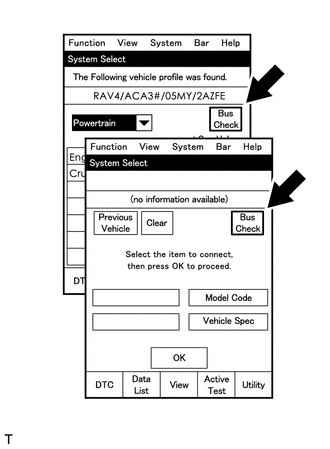
Select "Bus Check" from the "System Select" screen on the intelligent tester.
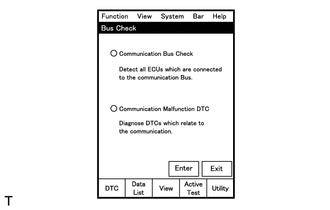
Select "Communication Malfunction DTC" from the "Bus Check" screen, and then select "Enter".
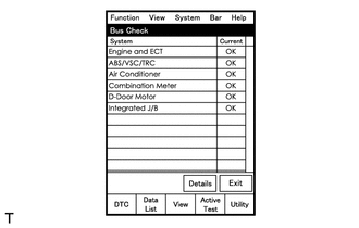
Select the system of the DTC to be checked and select "Details".
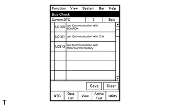
CAN communication system DTCs are displayed.
BUS CHECK (COMMUNICATION BUS CHECK)
- HINT:
-
The ECUs and sensors that are properly connected to the CAN communication system can be displayed using the intelligent tester.
Select "Communication Bus Check" from the "Bus Check" screen.
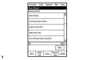
The screen displays the ECUs and sensors that are properly connected to the CAN communication system.
- HINT:
-
If any properly connected ECUs or sensors are not displayed, there is a communication stop in the system (See page Power Source / Network>CAN COMMUNICATION>CAN COMMUNICATION SYSTEM>PROBLEM SYMPTOMS TABLE).
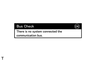
"There is no system connected to the communication bus" is displayed if there are no ECUs or sensors connected to the CAN bus.
CHECK INSTALLED SYSTEMS (ECUS AND SENSORS) THAT USE CAN COMMUNICATION
Systems (ECUs and sensors) that use CAN communication vary depending on the vehicle's optional settings. Check which systems (ECUs and sensors) are installed on the vehicle.
| ECU / Sensor name | Installed to |
|---|---|
| Brake actuator assembly (skid control ECU) | Vehicles without VSC |
| ABS and traction actuator (skid control ECU) | Vehicles with VSC |
| Steering angle sensor | Vehicles with VSC or AFS |
| Yaw rate sensor | Vehicles with VSC |
| Air conditioning amplifier | All vehicles |
| ECM | All vehicles |
| Center airbag sensor assembly | All vehicles |
| Power steering ECU | All vehicles |
| Main body ECU | All vehicles |
| Combination meter ECU | All vehicles |
| Network gateway ECU | for RHD |
| AFS ECU | Vehicles with AFS |
| Navigation receiver assembly | Vehicles with navigation system |
| Power slide door ECU RH | Vehicles with power slide door system |
| Power slide door ECU LH | Vehicles with power slide door system |
| Power back door ECU | Vehicles with power back door system |
| Certification ECU | All vehicles |
DTC TABLE BY ECU
- HINT:
- ·
In the CAN communication system, CAN communication system DTCs output by the ECU can be displayed by using the intelligent tester.
·If CAN communication system DTCs are output, the malfunction cannot be determined solely from the DTCs. Perform troubleshooting according to "HOW TO PROCEED WITH TROUBLESHOOTING" (See page Power Source / Network>CAN COMMUNICATION>CAN COMMUNICATION SYSTEM>HOW TO PROCEED WITH TROUBLESHOOTING).
BRAKE ACTUATOR (SKID CONTROL ECU)
For vehicles without VSC only.
- HINT:
-
DTC communication uses the CAN communication system.
| DTC No. | Detection Item |
|---|---|
| U0073/94 | Control Module Communication Bus OFF |
ABS AND TRACTION ACTUATOR (SKID CONTROL ECU)
For vehicles with VSC only.
- HINT:
-
DTC communication uses the CAN communication system.
| DTC No. | Detection Item |
|---|---|
| U0073/94 | Control Module Communication Bus OFF |
| U0100/65 | Lost Communication with ECM / PCM |
| U0123/62 | Lost Communication with Yaw Rate Sensor Module |
| U0126/63 | Lost Communication with Steering Angle Sensor Module |
POWER STEERING ECU
- HINT:
-
DTC communication uses the CAN communication system.
| DTC No. | Detection Item |
|---|---|
| U0100 | Lost Communication with ECM/PCM "A" |
| U0129 | Lost Communication with Brake System Control Module |
ECM
- HINT:
-
DTC communication uses the CAN communication system.
| DTC No. | Detection Item |
|---|---|
| U0101* | Lost Communication with TCM |
| U0129 | Lost Communication with Skid Control ECU |
- HINT:
*: Refer to SFI System (for 2GR-FE) (See page Engine / Hybrid System>2GR-FE ENGINE CONTROL>SFI SYSTEM>U0101)
TCM / Intelligent Tester Display "ECT"
- HINT:
-
DTC communication uses the CAN communication system.
| DTC No. | Detection Item |
|---|---|
| U0100 | Lost Communication with ECM / PCM "A" |
- HINT:
*: Refer to Automatic Transaxle System (See page Drivetrain>U660E (AUTOMATIC TRANSMISSION / TRANSAXLE)>AUTOMATIC TRANSAXLE SYSTEM>U0100)
AIR CONDITIONING AMPLIFIER
- HINT:
-
DTC communication uses the CAN communication system.
| DTC No. | Detection Item |
|---|---|
| B1499/99 | Multiplex Communication Circuit |
COMBINATION METER ECU
- HINT:
-
DTC communication uses the CAN communication system.
| DTC No. | Detection Item |
|---|---|
| U0100 | Lost Communication with ECM/PCM "A" |
| U0129 | Lost Communication with Skid Control ECU |
MAIN BODY ECU
- HINT:
-
DTC communication uses the CAN communication system.
| DTC No. | Detection Item |
|---|---|
| B1207 | Certification ECU Communication Malfunction |
| B1216 | Rear Door ECU RH Communication Stop |
| B1217 | Rear Door ECU LH Communication Stop |
| B1287 | Back Door ECU Communication Stop |
| B2326 | CAN MS Bus Line Communication Malfunction |
NETWORK GATEWAY ECU (for RHD)
- HINT:
-
DTC communication uses the CAN communication system.
DTC No. Detection Item U0182 Lost Communication with AFS ECU U1002 Lost Communication with Gateway Module
AFS ECU
For vehicles with AFS only.
- HINT:
-
DTC communication uses the CAN communication system.
| DTC No. | Detection Item |
|---|---|
| B2427 | CAN Communication Malfunction |
NAVIGATION RECEIVER ASSEMBLY
For vehicles with navigation system only.
- HINT:
-
DTC communication uses the CAN communication system.
| DTC No. | Detection Item |
|---|---|
| U0073 | Sending Malfunction |
| U0100 | Lost Communication with ECM |
| U0126 | Lost Communication with Steering Angle Sensor Module |
| U0140 | Lost Communication with Body Control Module |
| U0155 | Meter ECU Communication |
CENTER AIRBAG SENSOR
- HINT:
-
The center airbag sensor is connected to the CAN communication system but CAN communication DTCs are not output.
CERTIFICATION ECU
- HINT:
-
The certification ECU is connected to the CAN communication system but CAN communication DTCs are not output.
POWER SLIDE DOOR ECU LH
For vehicles with power slide door system only.
- HINT:
-
The power slide door ECU LH is connected to the CAN communication system but CAN communication DTCs are not output.
POWER SLIDE DOOR ECU RH
For vehicles with power slide door system only.
- HINT:
-
The power slide door ECU RH is connected to the CAN communication system but CAN communication DTCs are not output.
POWER BACK DOOR ECU
For vehicles with power back door system only.
- HINT:
-
The power back door ECU is connected to the CAN communication system but CAN communication DTCs are not output.
DTC COMBINATION TABLE
| Output from | Output DTC | Detection Item | Detected Communication Stop Mode | |||||
|---|---|---|---|---|---|---|---|---|
| CAN No. 1 Bus Circuit | ||||||||
| BRAKE ACTUATOR ASSEMBLY (SKID CONTROL ECU) COMMUNICATION STOP MODE | ABS AND TRACTION ACTUATOR (SKID CONTROL ECU) COMMUNICATION STOP MODE | POWER STEERING ECU COMMUNICATION STOP MODE | STEERING ANGLE SENSOR COMMUNICATION STOP MODE | YAW RATE SENSOR COMMUNICATION STOP MODE | ECM COMMUNICATION STOP MODE | |||
| Brake Actuator Assembly (Skid Control ECU) | U0073/94 | Control Module Communication Bus OFF | ▲ | ▲ | ○ | ▲ | ▲ | ▲ |
| ABS and Traction Actuator (Skid Control ECU) | U0073/94 | Control Module Communication Bus OFF | ▲ | ▲ | ○ | ▲ | ▲ | ▲ |
| U0100/65 | Lost Communication with ECM / PCM | ▲ | ○ | ▲ | ▲ | ▲ | ○ | |
| U0123/62 | Lost Communication with Yaw Rate Sensor Module | ▲ | ○ | ▲ | ▲ | ○ | ▲ | |
| U0126/63 | Lost Communication with Steering Angle Sensor Module | ▲ | ○ | ▲ | ○ | ▲ | ▲ | |
| Power Steering ECU | U0100 | Lost Communication with ECM/PCM "A" | ▲ | ▲ | ○ | ▲ | ▲ | ○ |
| U0129 | Lost Communication with Brake System Control Module | ○ | ○ | ○ | ▲ | ▲ | ▲ | |
| Steering Angle Sensor | - | - | X | X | X | X | X | X |
| Yaw Rate Sensor | - | - | X | X | X | X | X | X |
| ECM | U0129 | Lost Communication with Brake System Control Module | ○ | ○ | ▲ | ▲ | ▲ | ○ |
| Center Airbag Sensor | - | - | X | X | X | X | X | X |
| Air Conditioning Amplifier | B1499/99 | Multiplex Communication Circuit | ▲ | ▲ | ▲ | ▲ | ▲ | ○ |
| Combination Meter ECU | U0100 | Lost Communication with ECM/PCM "A" | ▲ | ▲ | ▲ | ▲ | ▲ | ○ |
| U0129 | Lost Communication with Skid Control ECU | ○ | ○ | ▲ | ▲ | ▲ | ▲ | |
| Network Gateway ECU*1 | U1002 | Lost Communication with Gateway Module | X | X | X | X | X | X |
| U0182 | Lost Communication with AFS ECU | X | X | X | X | X | X | |
| AFS ECU | B2427 | CAN Communication Malfunction | ▲ | ▲ | ▲ | ○ | ▲ | ▲ |
| Navigation Receiver Assembly*2 | U0073 | Sending Malfunction | ▲ | ▲ | ▲ | ▲ | ▲ | ▲ |
| U0100 | Lost Communication with ECM | ▲ | ▲ | ▲ | ▲ | ▲ | ○ | |
| U0126 | Lost Communication with Steering Angle Sensor Module | ▲ | ▲ | ▲ | ○ | ▲ | ▲ | |
| U0140 | Lost Communication with Body Control Module | ▲ | ▲ | ▲ | ▲ | ▲ | ▲ | |
| U0155 | Meter ECU Communication | ▲ | ▲ | ▲ | ▲ | ▲ | ▲ | |
| Main Body ECU | B1207 | Certification ECU Communication Malfunction | X | X | X | X | X | X |
| B1216 | Rear Door ECU RH Communication Stop | X | X | X | X | X | X | |
| B1217 | Rear Door ECU LH Communication Stop | X | X | X | X | X | X | |
| B1287 | Back Door ECU Communication Stop | X | X | X | X | X | X | |
| B2326 | CAN MS Bus Line Communication Malfunction | X | X | X | X | X | X | |
| Certification ECU | - | - | X | X | X | X | X | X |
| Power Slide Door ECU RH | - | - | X | X | X | X | X | X |
| Power Slide Door ECU LH | - | - | X | X | X | X | X | X |
| Power Back Door ECU | - | - | X | X | X | X | X | X |
- HINT:
- ·
○: Output under condition shown in table above
·▲: Only when one side has an open circuit
·X: Not output
·The air conditioning amplifier and navigation receiver assembly only store present DTCs.
·*1: for RHD only
·*2: for LHD only
| Output from | Output DTC | Detection Item | Detected Communication Stop Mode | ||||||
|---|---|---|---|---|---|---|---|---|---|
| CAN No. 1 Bus Circuit | |||||||||
| CENTER AIRBAG SENSOR COMMUNICATION STOP MODE | AIR CONDITIONING AMPLIFIER COMMUNICATION STOP MODE | COMBINATION METER ECU COMMUNICATION STOP MODE | MAIN BODY ECU COMMUNICATION STOP MODE | GATEWAY ECU COMMUNICATION STOP MODE*1 | NAVIGATION ECU COMMUNICATION STOP MODE*2 | AFS ECU COMMUNICATION STOP MODE*2 | |||
| Brake Actuator Assembly (Skid Control ECU) | U0073/94 | Control Module Communication Bus OFF | ▲ | ▲ | ▲ | ▲ | ▲ | ▲ | ▲ |
| ABS and Traction Actuator (Skid Control ECU) | U0073/94 | Control Module Communication Bus OFF | ▲ | ▲ | ▲ | ▲ | ▲ | ▲ | ▲ |
| U0100/65 | Lost Communication with ECM / PCM | ▲ | ▲ | ▲ | ▲ | ▲ | ▲ | ▲ | |
| U0123/62 | Lost Communication with Yaw Rate Sensor Module | ▲ | ▲ | ▲ | ▲ | ▲ | ▲ | ▲ | |
| U0126/63 | Lost Communication with Steering Angle Sensor Module | ▲ | ▲ | ▲ | ▲ | ▲ | ▲ | ▲ | |
| Power Steering ECU | U0100 | Lost Communication with ECM/PCM "A" | ▲ | ▲ | ▲ | ▲ | ▲ | ▲ | ▲ |
| U0129 | Lost Communication with Brake System Control Module | ▲ | ▲ | ▲ | ▲ | ▲ | ▲ | ▲ | |
| Steering Angle Sensor | - | - | X | X | X | X | X | X | X |
| Yaw Rate Sensor | - | - | X | X | X | X | X | X | X |
| ECM | U0129 | Lost Communication with Brake System Control Module | ▲ | ▲ | ▲ | ▲ | ▲ | ▲ | ▲ |
| Center Airbag Sensor | - | - | X | X | X | X | X | X | X |
| Air Conditioning Amplifier | B1499/99 | Multiplex Communication Circuit | ▲ | ○ | ○ | ▲ | ▲ | ▲ | ▲ |
| Combination Meter ECU | U0100 | Lost Communication with ECM/PCM "A" | ▲ | ▲ | ○ | ▲ | ▲ | ▲ | ▲ |
| U0129 | Lost Communication with Skid Control ECU | ▲ | ▲ | ○ | ▲ | ▲ | ▲ | ▲ | |
| Network Gateway ECU*1 | U1002 | Lost Communication with Gateway Module | X | X | X | X | X | X | X |
| U0182 | Lost Communication with AFS ECU | X | X | X | X | X | X | X | |
| AFS ECU | B2427 | CAN Communication Malfunction | ▲ | ▲ | ▲ | ○ | ▲ | ▲ | ○ |
| Navigation Receiver Assembly*2 | U0073 | Sending Malfunction | ▲ | ▲ | ▲ | ▲ | ▲ | ○ | ▲ |
| U0100 | Lost Communication with ECM | ▲ | ▲ | ▲ | ▲ | ▲ | ○ | ▲ | |
| U0126 | Lost Communication with Steering Angle Sensor Module | ▲ | ▲ | ▲ | ▲ | ▲ | ○ | ▲ | |
| U0140 | Lost Communication with Body Control Module | ▲ | ▲ | ▲ | ○ | ▲ | ○ | ▲ | |
| U0155 | Meter ECU Communication | ▲ | ▲ | ○ | ▲ | ▲ | ○ | ▲ | |
| Main Body ECU | B1207 | Certification ECU Communication Malfunction | X | X | X | X | X | X | X |
| B1216 | Rear Door ECU RH Communication Stop | X | X | X | X | X | X | X | |
| B1217 | Rear Door ECU LH Communication Stop | X | X | X | X | X | X | X | |
| B1287 | Back Door ECU Communication Stop | X | X | X | X | X | X | X | |
| B2326 | CAN MS Bus Line Communication Malfunction | X | X | X | X | X | X | X | |
| Certification ECU | - | - | X | X | X | X | X | X | X |
| Power Slide Door ECU RH | - | - | X | X | X | X | X | X | X |
| Power Slide Door ECU LH | - | - | X | X | X | X | X | X | X |
| Power Back Door ECU | - | - | X | X | X | X | X | X | X |
- HINT:
- ·
○: Output under condition shown in table above
·▲: Only when one side has an open circuit
·X: Not output
·The air conditioning amplifier and navigation receiver assembly only store present DTCs.
·*1: for RHD only
·*2: for LHD only
| Output from | Output DTC | Detection Item | Detected Communication Stop Mode | |
|---|---|---|---|---|
| CAN No. 2 Bus Circuit | ||||
| GATEWAY ECU COMMUNICATION STOP MODE | AFS ECU COMMUNICATION STOP MODE*1 | |||
| Brake Actuator Assembly (Skid Control ECU) | U0073/94 | Control Module Communication Bus OFF | X | X |
| ABS and Traction Actuator (Skid Control ECU) | U0073/94 | Control Module Communication Bus OFF | X | X |
| U0100/65 | Lost Communication with ECM / PCM | X | X | |
| U0123/62 | Lost Communication with Yaw Rate Sensor Module | X | X | |
| U0126/63 | Lost Communication with Steering Angle Sensor Module | X | X | |
| Power Steering ECU | U0100 | Lost Communication with ECM/PCM "A" | X | X |
| U0129 | Lost Communication with Brake System Control Module | X | X | |
| Steering Angle Sensor | - | - | X | X |
| Yaw Rate Sensor | - | - | X | X |
| ECM | U0129 | Lost Communication with Brake System Control Module | X | X |
| Center Airbag Sensor | - | - | X | X |
| Air Conditioning Amplifier | B1499/99 | Multiplex Communication Circuit | X | X |
| Combination Meter ECU | U0100 | Lost Communication with ECM/PCM "A" | X | X |
| U0129 | Lost Communication with Skid Control ECU | X | X | |
| Network Gateway ECU*1 | U1002 | Lost Communication with Gateway Module | ○ | X |
| U0182 | Lost Communication with AFS ECU | ○ | ○ | |
| AFS ECU | B2427 | CAN Communication Malfunction | ○ | ○ |
| Navigation Receiver Assembly*2 | U0073 | Sending Malfunction | X | X |
| U0100 | Lost Communication with ECM | X | X | |
| U0126 | Lost Communication with Steering Angle Sensor Module | X | X | |
| U0140 | Lost Communication with Body Control Module | X | X | |
| U0155 | Meter ECU Communication | X | X | |
| Main Body ECU | B1207 | Certification ECU Communication Malfunction | X | X |
| B1216 | Rear Door ECU RH Communication Stop | X | X | |
| B1217 | Rear Door ECU LH Communication Stop | X | X | |
| B1287 | Back Door ECU Communication Stop | X | X | |
| B2326 | CAN MS Bus Line Communication Malfunction | X | X | |
| Certification ECU | - | - | X | X |
| Power Slide Door ECU RH | - | - | X | X |
| Power Slide Door ECU LH | - | - | X | X |
| Power Back Door ECU | - | - | X | X |
- HINT:
- ·
○: Output under condition shown in table above
·X: Not output
·The air conditioning amplifier and navigation receiver assembly only store present DTCs.
·The CAN No. 2 Bus is used on RHD only
·*1: for RHD only
·*2: for LHD only
| Output from | Output DTC | Detection Item | Detected Communication Stop Mode | ||||
|---|---|---|---|---|---|---|---|
| CAN MS Bus Circuit | |||||||
| MAIN BODY ECU COMMUNICATION STOP MODE | CERTIFICATION ECU COMMUNICATION STOP MODE | POWER SLIDE DOOR ECU RH COMMUNICATION STOP MODE | POWER SLIDE DOOR ECU LH COMMUNICATION STOP MODE | POWER BACK DOOR ECU COMMUNICATION STOP MODE | |||
| Brake Actuator Assembly (Skid Control ECU) | U0073/94 | Control Module Communication Bus OFF | X | X | X | X | X |
| ABS and Traction Actuator (Skid Control ECU) | U0073/94 | Control Module Communication Bus OFF | X | X | X | X | X |
| U0100/65 | Lost Communication with ECM / PCM | X | X | X | X | X | |
| U0123/62 | Lost Communication with Yaw Rate Sensor Module | X | X | X | X | X | |
| U0126/63 | Lost Communication with Steering Angle Sensor Module | X | X | X | X | X | |
| Power Steering ECU | U0100 | Lost Communication with ECM/PCM "A" | X | X | X | X | X |
| U0129 | Lost Communication with Brake System Control Module | X | X | X | X | X | |
| Steering Angle Sensor | - | - | X | X | X | X | X |
| Yaw Rate Sensor | - | - | X | X | X | X | X |
| ECM | U0129 | Lost Communication with Brake System Control Module | X | X | X | X | X |
| Center Airbag Sensor | - | - | X | X | X | X | X |
| Air Conditioning Amplifier | B1499/99 | Multiplex Communication Circuit | X | X | X | X | X |
| Combination Meter ECU | U0100 | Lost Communication with ECM/PCM "A" | X | X | X | X | X |
| U0129 | Lost Communication with Skid Control ECU | X | X | X | X | X | |
| Network Gateway ECU*1 | U1002 | Lost Communication with Gateway Module | X | X | X | X | X |
| U0182 | Lost Communication with AFS ECU | X | X | X | X | X | |
| AFS ECU | B2427 | CAN Communication Malfunction | X | X | X | X | X |
| Navigation Receiver Assembly*2 | U0073 | Sending Malfunction | X | X | X | X | X |
| U0100 | Lost Communication with ECM | X | X | X | X | X | |
| U0126 | Lost Communication with Steering Angle Sensor Module | X | X | X | X | X | |
| U0140 | Lost Communication with Body Control Module | X | X | X | X | X | |
| U0155 | Meter ECU Communication | X | X | X | X | X | |
| Main Body ECU | B1207 | Certification ECU Communication Malfunction | ○ | ○ | ▲ | ▲ | ▲ |
| B1216 | Rear Door ECU RH Communication Stop | ○ | ▲ | ○ | ▲ | ▲ | |
| B1217 | Rear Door ECU LH Communication Stop | ○ | ▲ | ▲ | ○ | ▲ | |
| B1287 | Back Door ECU Communication Stop | ○ | ▲ | ▲ | ▲ | ○ | |
| B2326 | CAN MS Bus Line Communication Malfunction | ○ | ▲ | ▲ | ▲ | ▲ | |
| Certification ECU | - | - | X | X | X | X | X |
| Power Slide Door ECU RH | - | - | X | X | X | X | X |
| Power Slide Door ECU LH | - | - | X | X | X | X | X |
| Power Back Door ECU | - | - | X | X | X | X | X |
- HINT:
- ·
○: Output under condition shown in table above
·▲: Only when one side has an open circuit
·X: Not output
·The air conditioning amplifier and navigation receiver assembly only store present DTCs.
·If the network gateway ECU is normal (CAN No. 2 bus circuit normal), but there is a communication malfunction code output regarding the area between the ECUs connected to the CAN No. 1 bus circuit and the ECUs connected to the CAN No. 2 bus circuit, inspect the network gateway ECU communication stop mode (CAN No. 1 bus circuit connection side branch wire open).
·If the main body ECU is normal (CAN MS bus circuit normal), but there is a communication malfunction code output regarding the area between the ECUs connected to the CAN No. 1 bus circuit and the ECUs connected to the CAN MS bus circuit, inspect the main body ECU communication stop mode (CAN No. 1 bus circuit connection side branch wire open).
·Except for the network gateway ECU, if the ECUs connected to the CAN No. 2 bus circuit have stored all possible malfunction codes, there may be a CAN No. 2 bus circuit main wire open or short malfunction (all communication stop).
·During a network malfunction (main wire malfunction), the network gateway ECU may erase stored DTCs in an attempt to reinstate communication.
·If the ECUs connected to the vehicle have stored all communication malfunction codes, follow the DTC U1002 inspection procedure and inspect the bus malfunction.
·Check the stop mode by using the results of the BUS CHECK for the center airbag sensor (See page Power Source / Network>CAN COMMUNICATION>CAN COMMUNICATION SYSTEM>Center Airbag Sensor Communication Stop Mode).
Perform troubleshooting according to the combination of DTCs output.
BRAKE ACTUATOR (SKID CONTROL ECU) COMMUNICATION STOP MODE: (See page Power Source / Network>CAN COMMUNICATION>CAN COMMUNICATION SYSTEM>Brake Actuator (Skid Control ECU) Communication Stop Mode)
ABS AND TRACTION ACTUATOR (SKID CONTROL ECU) COMMUNICATION STOP MODE: (See page Power Source / Network>CAN COMMUNICATION>CAN COMMUNICATION SYSTEM>ABS and Traction Actuator (Skid Control ECU) Communication Stop Mode)
POWER STEERING ECU COMMUNICATION STOP MODE: (See page Power Source / Network>CAN COMMUNICATION>CAN COMMUNICATION SYSTEM>Power Steering ECU Communication Stop Mode)
STEERING ANGLE SENSOR COMMUNICATION STOP MODE: (See page Power Source / Network>CAN COMMUNICATION>CAN COMMUNICATION SYSTEM>Steering Angle Sensor Communication Stop Mode)
YAW RATE SENSOR COMMUNICATION STOP MODE: (See page Power Source / Network>CAN COMMUNICATION>CAN COMMUNICATION SYSTEM>Yaw Rate Sensor Communication Stop Mode)
ECM COMMUNICATION STOP MODE: (See page Power Source / Network>CAN COMMUNICATION>CAN COMMUNICATION SYSTEM>ECM Communication Stop Mode)
AIR CONDITIONING AMPLIFIER COMMUNICATION STOP MODE: (See page Power Source / Network>CAN COMMUNICATION>CAN COMMUNICATION SYSTEM>Air Conditioning Amplifier Communication Stop Mode)
COMBINATION METER ECU COMMUNICATION SYSTEM: (See page Power Source / Network>CAN COMMUNICATION>CAN COMMUNICATION SYSTEM>Combination Meter ECU Communication Stop Mode)
MAIN BODY ECU COMMUNICATION STOP MODE: (See page Power Source / Network>CAN COMMUNICATION>CAN COMMUNICATION SYSTEM>Main Body ECU Communication Stop Mode)
GATEWAY ECU COMMUNICATION STOP MODE: (for RHD) (See page Power Source / Network>CAN COMMUNICATION>CAN COMMUNICATION SYSTEM>Gateway ECU Communication Stop Mode)
NAVIGATION ECU COMMUNICATION STOP MODE: (for LHD) (See page Power Source / Network>CAN COMMUNICATION>CAN COMMUNICATION SYSTEM>Navigation ECU Communication Stop Mode)
AFS ECU COMMUNICATION STOP MODE: (for LHD) (See page Power Source / Network>CAN COMMUNICATION>CAN COMMUNICATION SYSTEM>AFS ECU Communication Stop Mode)