METER / GAUGE / DISPLAY METER / GAUGE SYSTEM Odo/Trip Switch Malfunction
DESCRIPTION
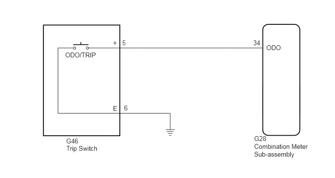
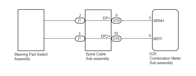
In this circuit, the combination meter sub-assembly receives an ODO/TRIP switch signal from the trip switch*1 or steering pad switch assembly*2 via a direct line.
- HINT:
-
*1: w/o Multi-information Display
-
*2: w/ Multi-information Display
WIRING DIAGRAM
w/o Multi-information Display
w/ Multi-information Display
PROCEDURE
Connect the GTS to the DLC3.
Turn the engine switch on (IG).
Turn the GTS on.
Enter the following menus: Body Electrical / Combination Meter / Data List.
Read the Data List according to the display on the GTS.
| Tester Display | Measurement Item/Range | Normal Condition | Diagnostic Note |
|---|---|---|---|
| ODO/TRIP Change SW | ODO/TRIP switch / ON or OFF | ON: Switch pushed
OFF: Switch released |
- |
- OK:
ODO/TRIP switch condition displayed on the GTS changes with the actual switch operation.
OK
NG
Choose the model to be inspected.
- Result:
Result Proceed to w/o Multi-information Display A w/ Multi-information Display B
A
B
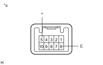
Remove the trip switch (see page Vehicle Interior>LIGHTING>HAZARD WARNING SWITCH>REMOVAL).
Measure the resistance according to the value(s) in the table below.
- Standard Resistance:
Tester Connection Condition Specified Condition 5 (+) - 6 (E) ODO/TRIP switch is pressed Below 1 Ω ODO/TRIP switch is not pressed 10 kΩ or higher
| *a | Component without harness connected
(Trip Switch) |
OK
NG
Disconnect the G28 combination meter sub-assembly connector.
Measure the resistance according to the value(s) in the table below.
- Standard Resistance:
Tester Connection Condition Specified Condition G28-34 (ODO) - G46-5 (+) Always Below 1 Ω G28-34 (ODO) or G46-5 (+) - Body ground Always 10 kΩ or higher G46-6 (E) - Body ground Always Below 1 Ω
OK
NG
Remove the steering pad switch assembly (see page Audio / Visual / Telematics>AUDIO / VIDEO>STEERING PAD SWITCH>REMOVAL).
Inspect the steering pad switch assembly (see page Audio / Visual / Telematics>AUDIO / VIDEO>STEERING PAD SWITCH>INSPECTION).
OK
NG
Remove the spiral cable sub-assembly (see page Vehicle Interior>SUPPLEMENTAL RESTRAINT SYSTEMS>SPIRAL CABLE>REMOVAL).
Inspect the spiral cable sub-assembly (see page Vehicle Interior>SUPPLEMENTAL RESTRAINT SYSTEMS>SPIRAL CABLE>INSPECTION).
OK
NG
Disconnect the G28 combination meter sub-assembly connector.
Measure the resistance according to the value(s) in the table below.
- Standard Resistance:
Tester Connection Condition Specified Condition G28-5 (MSM+) - G10-9 (DP+) Always Below 1 Ω G28-5 (MSM+) or G10-9 (DP+) - Body ground Always 10 kΩ or higher G28-6 (MSTI) - G10-10 (DP2+) Always Below 1 Ω G28-6 (MSTI) or G10-10 (DP2+) - Body ground Always 10 kΩ or higher
OK
NG