Home › Audio / Visual / Telematics › PARK ASSIST / MONITORING › TOYOTA PARKING ASSIST-SENSOR SYSTEM(for RHD) › from 2016.05
RM24M0E _56 Audio / Visual / Telematics _059590 PARK ASSIST / MONITORING _0292210 TOYOTA PARKING ASSIST-SENSOR SYSTEM(for RHD) C

PARK ASSIST / MONITORING  TOYOTA PARKING ASSIST-SENSOR SYSTEM(for RHD)  C1AED  Rear Sensor Communication Malfunction  


DESCRIPTION

This DTC is stored when there is an open or short circuit in the communication line between the rear sensors and the clearance warning ECU assembly, or when there is a malfunction in a rear sensor.

DTC No. DTC Detection Condition Trouble Area
C1AED An open or short circuit in the communication line between the rear sensors and clearance warning ECU assembly or a malfunction in a rear sensor during initialization mode after the engine switch is turned on (IG).
·

Rear sensor circuit

·

Clearance warning ECU assembly


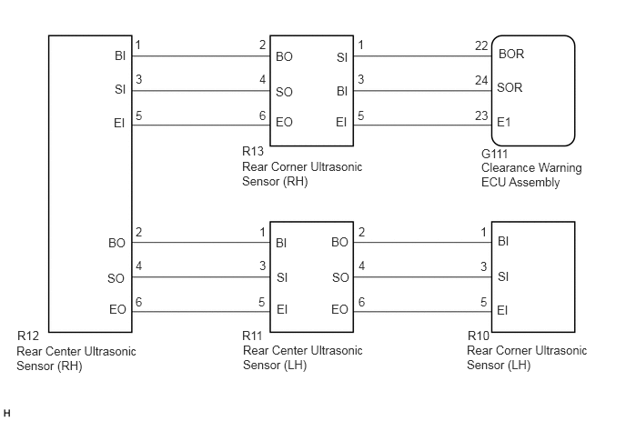
WIRING DIAGRAM

E211788E49
2.781,3.927 4.406,4.281 1.625,0.354 10 false Rear Center Ultrasonic Sensor (LH) 5.344,3.927 6.76,4.417 1.417,0.49 10 false Rear Corner Ultrasonic Sensor (LH) 0.188,3.938 1.615,4.438 1.427,0.5 10 false Rear Center Ultrasonic Sensor (RH) 3.854,0.958 4.021,1.24 0.167,0.281 10 false BI 3.844,1.313 4.042,1.563 0.198,0.25 10 false EI 3.854,0.573 4.042,0.854 0.188,0.281 10 false SI 3.156,0.563 3.438,0.823 0.281,0.26 10 false BO 3.156,1.313 3.427,1.552 0.271,0.24 10 false EO 3.156,0.969 3.427,1.24 0.271,0.271 10 false SO 1.313,0.552 1.521,0.792 0.208,0.24 10 false BI 1.302,1.323 1.5,1.563 0.198,0.24 10 false EI 1.313,0.938 1.51,1.177 0.198,0.24 10 false SI 1.24,2.698 1.479,2.938 0.24,0.24 10 false BO 1.25,3.458 1.531,3.75 0.281,0.292 10 false EO 1.229,3.104 1.448,3.375 0.219,0.271 10 false SO 5.688,3.469 5.917,3.729 0.229,0.26 10 false EI 5.698,3.083 5.917,3.302 0.219,0.219 10 false SI 5.698,2.677 5.896,2.906 0.198,0.229 10 false BI 4.094,0.427 4.25,0.583 0.156,0.156 10 false 1 2.969,0.823 3.073,0.979 0.104,0.156 10 false 4 2.969,0.427 3.073,0.583 0.104,0.156 10 false 2 4.094,1.24 4.25,1.396 0.156,0.156 10 false 5 4.094,0.823 4.25,0.979 0.156,0.156 10 false 3 2.969,1.24 3.073,1.396 0.104,0.156 10 false 6 1.542,0.427 1.698,0.583 0.156,0.156 10 false 1 1.552,2.958 1.708,3.115 0.156,0.156 10 false 4 1.552,2.573 1.708,2.729 0.156,0.156 10 false 2 1.552,1.24 1.708,1.396 0.156,0.156 10 false 5 1.552,0.823 1.708,0.979 0.156,0.156 10 false 3 1.552,3.375 1.708,3.531 0.156,0.156 10 false 6 5.5,2.573 5.604,2.729 0.104,0.156 10 false 1 5.5,3.375 5.604,3.531 0.104,0.156 10 false 5 5.5,2.969 5.604,3.125 0.104,0.156 10 false 3 3.156,2.698 3.354,2.958 0.198,0.26 10 false BI 3.167,3.458 3.344,3.708 0.177,0.25 10 false EI 3.167,3.094 3.354,3.406 0.188,0.313 10 false SI 3.792,2.688 4,2.938 0.208,0.25 10 false BO 3.792,3.458 4.052,3.74 0.26,0.281 10 false EO 3.802,3.094 4.031,3.375 0.229,0.281 10 false SO 4.104,2.573 4.26,2.729 0.156,0.156 10 false 2 2.969,2.958 3.073,3.115 0.104,0.156 10 false 3 2.969,2.573 3.073,2.729 0.104,0.156 10 false 1 4.104,3.375 4.26,3.531 0.156,0.156 10 false 6 4.104,2.958 4.26,3.115 0.156,0.156 10 false 4 2.958,3.375 3.063,3.531 0.104,0.156 10 false 5 2.771,3.76 3.031,3.927 0.26,0.167 10 false R11 0.198,3.76 0.49,3.927 0.292,0.167 10 false R12 5.51,1.833 6.74,2.167 1.229,0.333 10 false Clearance Warning ECU Assembly 5.708,0.531 6.125,0.781 0.417,0.25 10 false BOR 5.688,1.313 6.104,1.594 0.417,0.281 10 false E1 5.688,0.917 6.146,1.208 0.458,0.292 10 false SOR 5.438,0.438 5.625,0.594 0.188,0.156 10 false 22 5.438,1.24 5.615,1.396 0.177,0.156 10 false 23 5.438,0.833 5.615,0.99 0.177,0.156 10 false 24 5.51,1.677 5.979,1.844 0.469,0.167 10 false G111 5.354,3.76 5.625,3.927 0.271,0.167 10 false R10 2.771,1.823 4.177,2.24 1.406,0.417 10 false Rear Corner Ultrasonic Sensor (RH) 2.771,1.646 3.073,1.813 0.302,0.167 10 false R13

PROCEDURE

1.CHECK DTC OUTPUT (C1AED)

A

2.CHECK HARNESS AND CONNECTOR (CLEARANCE WARNING ECU ASSEMBLY - REAR CORNER ULTRASONIC SENSOR (RH))

B

2.CHECK HARNESS AND CONNECTOR (CLEARANCE WARNING ECU ASSEMBLY - REAR CORNER ULTRASONIC SENSOR (RH))
a.

Disconnect the G111 clearance warning ECU assembly connector.


b.

Disconnect the R13 rear corner ultrasonic sensor (RH) connector.


c.

Measure the resistance according to the value(s) in the table below.

Standard Resistance:
Tester Connection Condition Specified Condition
G111-22 (BOR) - R13-1 (BI) Always Below 1 Ω
G111-24 (SOR) - R13-3 (SI) Always Below 1 Ω
G111-23 (E1) - R13-5 (EI) Always Below 1 Ω
G111-22 (BOR) - Body ground Always 10 kΩ or higher
G111-24 (SOR) - Body ground Always 10 kΩ or higher
G111-23 (E1) - Body ground Always 10 kΩ or higher


OK

3.CHECK HARNESS AND CONNECTOR (REAR CORNER ULTRASONIC SENSOR (RH) - REAR CENTER ULTRASONIC SENSOR (RH))

NG

REPAIR OR REPLACE HARNESS OR CONNECTOR

3.CHECK HARNESS AND CONNECTOR (REAR CORNER ULTRASONIC SENSOR (RH) - REAR CENTER ULTRASONIC SENSOR (RH))
a.

Disconnect the R12 rear center ultrasonic sensor (RH) connector.


b.

Measure the resistance according to the value(s) in the table below.

Standard Resistance:
Tester Connection Condition Specified Condition
R13-2 (BO) - R12-1 (BI) Always Below 1 Ω
R13-4 (SO) - R12-3 (SI) Always Below 1 Ω
R13-6 (EO) - R12-5 (EI) Always Below 1 Ω
R13-2 (BO) - Body ground Always 10 kΩ or higher
R13-4 (SO) - Body ground Always 10 kΩ or higher
R13-6 (EO) - Body ground Always 10 kΩ or higher


OK

4.CHECK HARNESS AND CONNECTOR (REAR CENTER ULTRASONIC SENSOR (RH) - REAR CENTER ULTRASONIC SENSOR (LH))

NG

REPAIR OR REPLACE HARNESS OR CONNECTOR

4.CHECK HARNESS AND CONNECTOR (REAR CENTER ULTRASONIC SENSOR (RH) - REAR CENTER ULTRASONIC SENSOR (LH))
a.

Disconnect the R11 rear center ultrasonic sensor (LH) connector.


b.

Measure the resistance according to the value(s) in the table below.

Standard Resistance:
Tester Connection Condition Specified Condition
R12-2 (BO) - R11-1 (BI) Always Below 1 Ω
R12-4 (SO) - R11-3 (SI) Always Below 1 Ω
R12-6 (EO) - R11-5 (EI) Always Below 1 Ω
R12-2 (BO) - Body ground Always 10 kΩ or higher
R12-4 (SO) - Body ground Always 10 kΩ or higher
R12-6 (EO) - Body ground Always 10 kΩ or higher


OK

5.CHECK HARNESS AND CONNECTOR (REAR CENTER ULTRASONIC SENSOR (LH) - REAR CORNER ULTRASONIC SENSOR (LH))

NG

REPAIR OR REPLACE HARNESS OR CONNECTOR

5.CHECK HARNESS AND CONNECTOR (REAR CENTER ULTRASONIC SENSOR (LH) - REAR CORNER ULTRASONIC SENSOR (LH))
a.

Disconnect the R10 rear corner ultrasonic sensor (LH) connector.


b.

Measure the resistance according to the value(s) in the table below.

Standard Resistance:
Tester Connection Condition Specified Condition
R11-2 (BO) - R10-1 (BI) Always Below 1 Ω
R11-4 (SO) - R10-3 (SI) Always Below 1 Ω
R11-6 (EO) - R10-5 (EI) Always Below 1 Ω
R11-2 (BO) - Body ground Always 10 kΩ or higher
R11-4 (SO) - Body ground Always 10 kΩ or higher
R11-6 (EO) - Body ground Always 10 kΩ or higher


OK

6.INSPECT REAR CORNER ULTRASONIC SENSOR (RH)

NG

REPAIR OR REPLACE HARNESS OR CONNECTOR

6.INSPECT REAR CORNER ULTRASONIC SENSOR (RH)
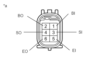
a.
E270573E05
1.958,0.896 2.375,0.479 false 1.958,1.115 2.656,1.115 false 1.958,1.365 2.417,1.74 false 0.948,0.563 1.5,0.896 false 0.823,1.115 1.5,1.115 false 1.021,1.75 1.479,1.354 false 2.729,1.031 3.042,1.229 0.313,0.198 10 false SI 2.479,0.375 2.792,0.573 0.313,0.198 10 false BI 2.51,1.667 2.823,1.865 0.313,0.198 10 false EI 0.552,1.052 0.865,1.25 0.313,0.198 10 false SO 0.615,0.458 0.927,0.656 0.313,0.198 10 false BO 0.771,1.698 1.083,1.896 0.313,0.198 10 false EO 0.115,0.115 0.427,0.313 0.313,0.198 10 false *a

Measure the resistance according to the value(s) in the table below.

Standard Resistance:
Tester Connection Condition Specified Condition
1 (BI) - 5 (EI) Always 10 kΩ or higher
1 (BI) - 2 (BO) Always 10 kΩ or higher
3 (SI) - 4 (SO) Always Below 1 Ω
5 (EI) - 6 (EO) Always Below 1 Ω


Text in Illustration
*a Component without harness connected
(Rear Corner Ultrasonic Sensor (RH))


OK

7.INSPECT REAR CENTER ULTRASONIC SENSOR (RH)

NG

7.INSPECT REAR CENTER ULTRASONIC SENSOR (RH)
a.
E270573E05
1.958,0.896 2.375,0.479 false 1.958,1.115 2.656,1.115 false 1.958,1.365 2.417,1.74 false 0.948,0.563 1.5,0.896 false 0.823,1.115 1.5,1.115 false 1.021,1.75 1.479,1.354 false 2.729,1.031 3.042,1.229 0.313,0.198 10 false SI 2.479,0.375 2.792,0.573 0.313,0.198 10 false BI 2.51,1.667 2.823,1.865 0.313,0.198 10 false EI 0.552,1.052 0.865,1.25 0.313,0.198 10 false SO 0.615,0.458 0.927,0.656 0.313,0.198 10 false BO 0.771,1.698 1.083,1.896 0.313,0.198 10 false EO 0.115,0.115 0.427,0.313 0.313,0.198 10 false *a

Measure the resistance according to the value(s) in the table below.

Standard Resistance:
Tester Connection Condition Specified Condition
1 (BI) - 5 (EI) Always 10 kΩ or higher
1 (BI) - 2 (BO) Always 10 kΩ or higher
3 (SI) - 4 (SO) Always Below 1 Ω
5 (EI) - 6 (EO) Always Below 1 Ω


Text in Illustration
*a Component without harness connected
(Rear Center Ultrasonic Sensor (RH))


OK

8.INSPECT REAR CENTER ULTRASONIC SENSOR (LH)

NG

8.INSPECT REAR CENTER ULTRASONIC SENSOR (LH)
a.
E270573E05
1.958,0.896 2.375,0.479 false 1.958,1.115 2.656,1.115 false 1.958,1.365 2.417,1.74 false 0.948,0.563 1.5,0.896 false 0.823,1.115 1.5,1.115 false 1.021,1.75 1.479,1.354 false 2.729,1.031 3.042,1.229 0.313,0.198 10 false SI 2.479,0.375 2.792,0.573 0.313,0.198 10 false BI 2.51,1.667 2.823,1.865 0.313,0.198 10 false EI 0.552,1.052 0.865,1.25 0.313,0.198 10 false SO 0.615,0.458 0.927,0.656 0.313,0.198 10 false BO 0.771,1.698 1.083,1.896 0.313,0.198 10 false EO 0.115,0.115 0.427,0.313 0.313,0.198 10 false *a

Measure the resistance according to the value(s) in the table below.

Standard Resistance:
Tester Connection Condition Specified Condition
1 (BI) - 5 (EI) Always 10 kΩ or higher
1 (BI) - 2 (BO) Always 10 kΩ or higher
3 (SI) - 4 (SO) Always Below 1 Ω
5 (EI) - 6 (EO) Always Below 1 Ω


Text in Illustration
*a Component without harness connected
(Rear Center Ultrasonic Sensor (LH))


OK

9.REPLACE REAR CORNER ULTRASONIC SENSOR (LH)

NG

9.REPLACE REAR CORNER ULTRASONIC SENSOR (LH)

NEXT

10.CHECK DTC OUTPUT (C1AED)

A

11.REPLACE REAR CENTER ULTRASONIC SENSOR (LH)

B

END (REAR CORNER ULTRASONIC SENSOR (LH) WAS DEFECTIVE)

11.REPLACE REAR CENTER ULTRASONIC SENSOR (LH)

NEXT

12.CHECK DTC OUTPUT (C1AED)

A

13.REPLACE REAR CENTER ULTRASONIC SENSOR (RH)

B

END (REAR CENTER ULTRASONIC SENSOR (LH) WAS DEFECTIVE)

13.REPLACE REAR CENTER ULTRASONIC SENSOR (RH)

NEXT

14.CHECK DTC OUTPUT (C1AED)

A

15.REPLACE REAR CORNER ULTRASONIC SENSOR (RH)

B

END (REAR CENTER ULTRASONIC SENSOR (RH) WAS DEFECTIVE)

15.REPLACE REAR CORNER ULTRASONIC SENSOR (RH)

NEXT

16.CHECK DTC OUTPUT (C1AED)

A

B

END (REAR CORNER ULTRASONIC SENSOR (RH) WAS DEFECTIVE)