C1210/36 Zero Point Calibration of Yaw Rate Sensor Undone
Diagnostic trouble codes · Vehicles built Jul 2007 – Oct 2010
Also covers:
- C1336/39 Zero Point Calibration of Acceleration Sensor Undone
DESCRIPTION
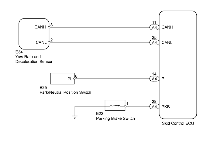
The skid control ECU receives signals from the yaw rate sensor and deceleration sensor via the CAN communication system.The deceleration sensor is built into the yaw rate sensor.
If there is trouble in the bus lines between the yaw rate sensor and deceleration sensor and the CAN communication system, the DTCs U0123/62 (yaw rate sensor communication trouble) and U0124/95 (deceleration sensor communication trouble) are output.
These DTCs are also output when the calibration has not been completed.
| DTC No. |
DTC Detecting Conditions |
Trouble Areas |
| C1210/36 |
When either of following 1 or 2 detected:
|
|
| C1336/39 |
When either of following 1 or 2 detected:
|
|
WIRING DIAGRAM

INSPECTION PROCEDURE
- HINT:
- When U0073/94, U0100/65, U0123/62, U0124/95 or U0126/63 are output accompanied by C1210/36 or C1336/39, inspect and repair the trouble areas indicated by U0073/94, U0100/65,U0123/62, U0124/95 or U0126/63 first.
| 1. PERFORM YAW RATE AND DECELERATION SENSOR ZERO POINT CALIBRATION |

Perform the zero point calibration of the yaw rate sensor and deceleration sensor (Click here).
| NEXT | |
 |
| 2. RECONFIRM DTC |
Clear the DTCs (Click here).
Check if the same DTCs are recorded (Click here).
- Result:
Result
Proceed to
DTC output
A
DTC not output
B
|
|
||||

| A | |
|
| 3. CHECK YAW RATE AND DECELERATION SENSOR INSTALLATION |
Check that the yaw rate and deceleration sensor has been installed properly (Click here).
- OK:
- The sensor is tightened to the specified torque.
The sensor is not tilted.
|
|
||||
| OK | |
|
| 4. CHECK HARNESS AND CONNECTOR (ECU - PARK/NEUTRAL POSITION SWITCH OR PARKING BRAKE SWITCH) |
A/T
Disconnect the skid control ECU connector.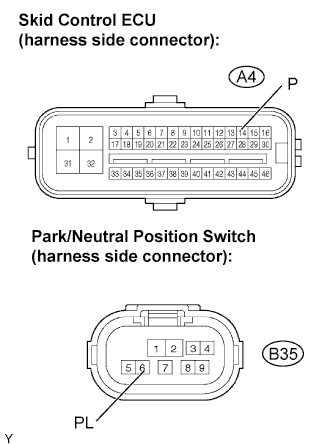
Disconnect the Park/Neutral position switch connector.
Measure the resistance.
- Standard resistance:
Tester Connection
Specified Condition
A4-14 (P) - B35-6 (PL)
Below 1 Ω
M/T:
Disconnect the skid control ECU connector.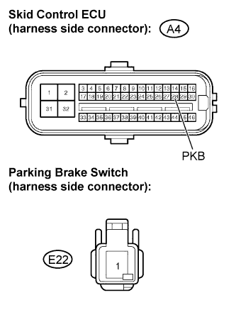
Disconnect the parking brake switch connector.
Measure the resistance.
- Standard resistance:
Tester Connection
Specified Condition
A4-28 (PKB) - E22-1
Below 1 Ω
|
|
||||
| OK | |
|
| 5. INSPECT PARK/NEUTRAL POSITION SWITCH (FOR A/T) OR PARKING BRAKE SWITCH (FOR M/T) |
Inspect the Park/Neutral Position (PNP) switch (for A/T models).
Disconnect the PNP switch connector.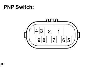
Check the resistance when the transmission gear selector lever is moved to each position.
- Standard resistance:
Gear Selector Lever Positions
Tester Connections
Specified Conditions
P
2 - 6, 4 - 5
Below 1 Ω
R
1 - 2
Below 1 Ω
N
2 - 9, 4 - 5
Below 1 Ω
D
2 - 7
Below 1 Ω
2
2 - 3
Below 1 Ω
L
2 - 8
Below 1 Ω
Inspect the parking brake switch (for M/T models).
Disconnect the parking brake switch connector.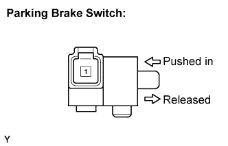
Measure the resistance.
- Standard resistance:
Tester Connection
Condition
Specified Condition
1 - Ground part
Parking brake switch ON
(Switch pin released)
Below 1 Ω
1 - Ground part
Parking brake switch OFF
(Switch pin pushed in)
10 kΩ or higher
|
|
||||
| OK | |
|
| 6. REPLACE YAW RATE AND DECELERATION SENSOR |
Replace the yaw rate and deceleration sensor (Click here).
| NEXT | |
|
| 7. PERFORM YAW RATE AND DECELERATION SENSOR ZERO POINT CALIBRATION |
Perform the zero point calibration of the yaw rate sensor and deceleration sensor (Click here).
| NEXT | |
|
| 8. RECONFIRM DTC |
Clear the DTCs (Click here).
Check if the same DTCs are recorded (Click here).
- Result:
Result
Proceed to
DTC output
A
DTC not output
B
|
|
||||
| A | ||
 |
||
| ||