C1210 Zero Point Calibration of Yaw Rate Sensor Undone
Diagnostic trouble codes · Vehicles built from Aug 2012
Also covers:
- C1336 Zero Point Calibration of Acceleration Sensor Undone
Versions by build date: Nov 2010 – Jul 2011 Aug 2011 – Jul 2012 from Aug 2012
DESCRIPTION
The skid control ECU receives signals from the yaw rate and deceleration sensor via the CAN communication system.The yaw rate sensor has a built-in deceleration sensor and detects the vehicle's condition using 2 circuits (GL1, GL2).
If there is trouble in the bus lines between the yaw rate and deceleration sensor and the CAN communication system, DTCs U0123 (yaw rate sensor communication trouble) and U0124 (deceleration sensor communication trouble) are stored.
The DTCs are also stored when the calibration has not been completed.
| DTC Code |
DTC Detection Condition |
Trouble Area |
| C1210 |
Zero point calibration of the yaw rate sensor is incomplete. |
|
| C1336 |
Zero point calibration of the deceleration sensor is incomplete. |
WIRING DIAGRAM
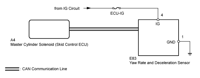

INSPECTION PROCEDURE
- NOTICE:
- When replacing the master cylinder solenoid, perform calibration (Click here).
- When replacing the yaw rate and deceleration sensor, perform zero point calibration (Click here)
- Inspect the fuses for circuits related to this system before performing the following inspection procedure.
- When replacing the master cylinder solenoid, perform calibration (Click here).
| 1. CHECK DTC (CAN COMMUNICATION SYSTEM) |

Check for DTCs (Click here).
Result Result
Proceed to
CAN DTC is not output
A
CAN DTC is output
B
|
|
||||

| A | |
 |
| 2. PERFORM ZERO POINT CALIBRATION OF YAW RATE AND DECELERATION SENSOR |
Perform zero point calibration of the yaw rate and deceleration sensor (Click here).
| NEXT | |
|
| 3. PERFORM TEST MODE (SIGNAL CHECK) |
Turn the ignition switch off.
Perform the signal check in the Test Mode Procedure (Click here).
- OK:
- All test mode DTCs are cleared.
|
|
||||

| OK | ||
 |
||
| ||
| 4. CHECK YAW RATE AND DECELERATION SENSOR INSTALLATION |
Turn the ignition switch off.
Check that the yaw rate and deceleration sensor has been installed properly (Click here).
- OK:
- The sensor is tightened to the specified torque.
- The sensor is not installed at an angle.
|
|
||||
| OK | |
|
| 5. READ VALUE USING INTELLIGENT TESTER (YAW RATE AND DECELERATION SENSOR) |
Turn the ignition switch off.
Connect the intelligent tester to the DLC3.
Turn the ignition switch to ON.
Turn the tester on.
Enter the following menus: Chassis / ABS/VSC/TRC / Data List.
ABS/VSC/TRC Tester Display
Measurement Item/Range
Normal Condition
Diagnostic Note
Deceleration Sensor
Deceleration sensor/ Min.: -18.183 m/s2, Max.: 18.183 m/s2
-
Changes continuously during acceleration/deceleration.
Deceleration Sensor2
Deceleration sensor 2/ Min.: -18.183 m/s2, Max.: 18.183 m/s2
-
Changes continuously during acceleration/deceleration.
Yaw Rate Sensor
Yaw rate sensor/ Min.: -128°/s, Max.: 127°/s
Vehicle stationary: 0°/s
Right turn: -128 to 0°/s
Left turn: 0 to 127°/s
-
Check that the yaw rate and deceleration sensor output value is displayed on the tester.
- OK:
- The yaw rate and deceleration sensor output value is normal.
- NOTICE:
- Check the yaw rate and deceleration sensor signal after replacement (Click here).
|
|
||||
| OK | ||
|
||
| ||