C1231/31 Steering Angle Sensor Circuit Malfunction
Diagnostic trouble codes · Vehicles built Aug 2009 – Oct 2010
Also covers:
- C1290/66 Steering Angle Sensor Zero Point Malfunction
Versions by build date: Jul 2007 – Jul 2009 Aug 2009 – Oct 2010
DESCRIPTION
The steering angle sensor signal is sent to the skid control ECU via the CAN communication system. When there is a malfunction in the communication system, the DTC will be detected by the diagnosis function.| DTC No. |
DTC Detecting Conditions |
Trouble Areas |
| C1231/31 |
When ECU IG1 terminal voltage 9.5 V or more, steering angle sensor malfunction signal received. |
|
| C1290/66 |
Steering angle sensor zero point calibration position significantly differs from recorded value. |
Steering angle sensor |
WIRING DIAGRAM
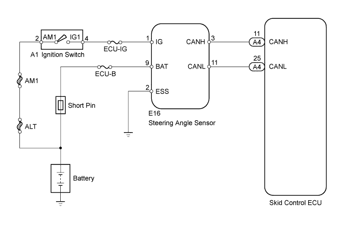

INSPECTION PROCEDURE
- NOTICE:
- When replacing the master cylinder solenoid, perform zero point calibration (Click here).
- HINT:
- When U0073/94, U0123/62, U0124/95 or U0126/63 are output together with C1231/31, inspect and repair the trouble areas indicated by U0073/94, U0123/62, U0124/95 or U0126/63 first.
- When the speed sensor or the yaw rate sensor has trouble, DTCs relating to the steering angle sensor may be output even when the steering angle sensor is normal. When DTCs relating to the speed sensor (C0200/31, C0205/32, C0210/33, C0215/34, C1235/35, C1236/36, C1238/38, C1239/39) or yaw rate (deceleration) sensor (C1232/32, C1234/34, C1243/43, C1244/44, C1245/45, C1381/97) are output together with other DTCs relating to the steering angle sensor, inspect and repair the speed sensor and yaw rate (deceleration) sensor first, and then inspect and repair the steering angle sensor.
- When U0073/94, U0123/62, U0124/95 or U0126/63 are output together with C1231/31, inspect and repair the trouble areas indicated by U0073/94, U0123/62, U0124/95 or U0126/63 first.
| 1. CHECK CAN COMMUNICATION SYSTEM |

Check for CAN communication system DTCs (Click here).
- Result:
Result
Proceed to
DTC not output
A
DTC output
B
|
|
||||

| A | |
 |
| 2. CHECK MOMENTARY INTERRUPTION (STEERING ANGLE SENSOR) |
Connect an intelligent tester to the DLC3.
Turn the ignition switch to ON.
Turn the tester on.
Using the intelligent tester, check for any momentary interruption in the wire harness and connector corresponding to a DTC.Select the following menu items: Chassis / ABS/VSC/TRC/ Data List
DATA LIST: ABS/VSC/TRC Tester Display
Measurement Item / Range
Normal Condition
Diagnostic Note
Steering Open
Steering angle sensor open detection :
OPN_DET or NORMAL
OPN_DET: Momentary interruption
NORMAL: Normal
-
- OK:
- There are no momentary interruptions.
- Result:
Result
Proceed to
OK (When troubleshooting in accordance with DTC CHART)
A
OK (When troubleshooting in accordance with PROBLEM SYMPTOMS TABLE)
B
NG
C
|
|
||||
|
|
||||

| A | |
|
| 3. RECONFIRM DTC |
Clear the DTCs (Click here).
Check if the same DTCs are recorded (Click here).
- Result:
Result
Proceed to
DTC output
A
DTC not output
B
|
|
||||
| A | ||
 |
||
| ||
| 4. CHECK TERMINAL VOLTAGE (STEERING ANGLE SENSOR) |
Remove the steering wheel and the column lower cover.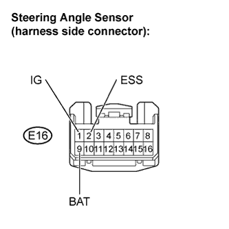
Disconnect the steering angle sensor connector.
Turn the ignition switch to ON.
Measure the voltage.
- Standard voltage:
Tester Connection
Specified Condition
E16-1 (IG) - E16-2 (ESS)
11 to 14 V
E16-9 (BAT) - E16-2 (ESS)
11 to 14 V
|
|
||||
| OK | |
|
| 5. REPLACE STEERING ANGLE SENSOR |
Replace the steering angle sensor (Click here).
| NEXT | |
|
| 6. RECONFIRM DTC |
Clear the DTCs (Click here).
Check if the same DTCs are recorded (Click here).
- Result:
Result
Proceed to
DTC output
A
DTC not output
B
|
|
||||
| A | ||
|
||
| ||