Brake Warning Light Remains ON
Circuit diagnosis · Vehicles built Jul 2007 – Jul 2009
Versions by build date: Jul 2007 – Jul 2009 Aug 2009 – Oct 2010 Nov 2010 – Jul 2011 from Aug 2011
DESCRIPTION
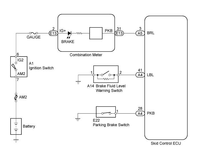
The BRAKE warning light lights up when the brake fluid is insufficient, the parking brake is applied or the EBD is defective.WIRING DIAGRAM

INSPECTION PROCEDURE
- NOTICE:
- When replacing the master cylinder solenoid, perform zero point calibration (Click here).
| 1. CHECK DTC |
 |
Check for the DTCs (Click here).
- Result:
Result
|
Proceed to
|
DTC not output
|
A
|
DTC output
|
B
|
|
B |
 |
|
| REPAIR CIRCUITS INDICATED BY OUTPUT DTCS (Click here)
|
|
|
| A |
|
 |
|
| 2. CHECK BRAKE FLUID LEVEL |
|
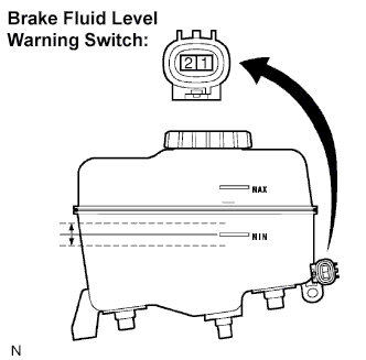
Check the amount of brake fluid in the brake reservoir.
- OK:
- Brake fluid level is correct.
|
NG |
|
|
|
|
| OK |
|
|
|
| 3. CHECK SKID CONTROL ECU CONNECTOR |
|
Check whether the skid control ECU connector is connected securely.
- OK:
- The skid control ECU connector is connected securely.
|
NG |
|
|
| CONNECT CONNECTOR CORRECTLY |
|
|
| OK |
|
|
|
| 4. INSPECT BRAKE FLUID LEVEL WARNING SWITCH |
|
- Disconnect the brake fluid level warning switch connector.
Measure the resistance.
- Standard resistance:
Tester Connection
|
Condition
|
Specified Condition
|
1 - 2
|
Float UP
|
1.9 k to 2.1 kΩ
|
1 - 2
|
Float DOWN
|
Below 1 Ω
|
- HINT:
- If the result is as specified, adjust the brake fluid level to the MAX level after measuring the resistance.
|
NG |
|
|
| REPLACE BRAKE MASTER CYLINDER RESERVOIR SUB-ASSEMBLY (Click here)
|
|
|
| OK |
|
|
|
| 5. CHECK HARNESS AND CONNECTOR (SKID CONTROL ECU - BRAKE FLUID LEVEL WARNING SWITCH) |
|
- Disconnect the skid control ECU connector.
Disconnect the brake fluid level warning switch connector.
Measure the resistance.
- Standard resistance:
Tester Connection
|
Specified Condition
|
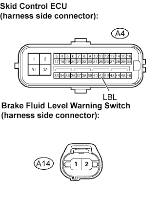
A4-41 (LBL) - A14-2
|
Below 1 Ω
|
A4-41 (LBL)- Body ground
|
10 kΩ or higher
|
|
NG |
|
|
| REPAIR OR REPLACE HARNESS OR CONNECTOR |
|
|
| OK |
|
|
|
| 6. INSPECT PARKING BRAKE SWITCH ASSEMBLY |
|
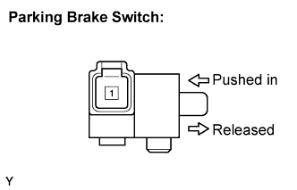
- Disconnect the parking brake switch connector.
Measure the resistance.
- Standard resistance:
Tester Connection
|
Switch Condition
|
Specified Condition
|
1 - Body ground
|
Released
|
Below 1 Ω
|
1 - Body ground
|
Pushed in
|
10 kΩ or higher
|
|
NG |
|
|
| REPLACE PARKING BRAKE SWITCH ASSEMBLY (Click here)
|
|
|
| OK |
|
|
|
| 7. CHECK HARNESS AND CONNECTOR (SKID CONTROL ECU - PARKING BRAKE SWITCH) |
|
- Disconnect the skid control ECU.
Disconnect the parking brake switch connector.
Measure the resistance.
- Standard resistance:
Tester Connection
|
Specified Condition
|
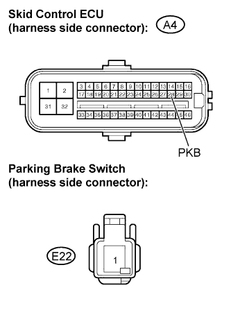
A4-28 (PKB) - E22-1
|
Below 1 Ω
|
A4-28 (PKB) - Body ground
|
10 kΩ or higher
|
|
NG |
|
|
| REPAIR OR REPLACE HARNESS OR CONNECTOR |
|
|
| OK |
|
|
|
| 8. CHECK HARNESS AND CONNECTOR (SKID CONTROL ECU - COMBINATION METER) |
|
- Disconnect the skid control ECU connector.
Disconnect the combination meter connector.
Measure the resistance.
- Standard resistance:
Tester Connection
|
Specified Condition
|
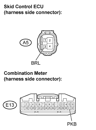
A5-3 (BRL) - E13-31 (PKB)
|
Below 1 Ω
|
A5-3 (BRL) - Body ground
|
10 kΩ or higher
|
|
NG |
|
|
| REPAIR OR REPLACE HARNESS OR CONNECTOR |
|
|
| OK |
|
|
|
| 9. INSPECT COMBINATION METER ASSEMBLY |
|
Check the combination meter system (Click here).
- OK:
- Combination meter is normal.
|
NG |
|
|
|
|
| OK |
|
 |
|
|