C1268/68 Transfer "L4" Position Switch Circuit
Diagnostic trouble codes · Vehicles built Jul 2007 – Jul 2009
Also covers:
- C1283/83 L4 Position Switch Malfunction (Test Mode DTC)
Versions by build date: Jul 2007 – Jul 2009 Aug 2009 – Oct 2010
DESCRIPTION
A-TRAC is activated if wheel skid is detected while the transfer is in the L4 position.| DTC No. |
DTC Detecting Condition |
Trouble Areas |
| C1268/68 |
L4 switch signal input to skid control ECU does not match L4 switch signal output from ECM. |
|
| C1283/83 |
Detected only during test mode |
|
WIRING DIAGRAM
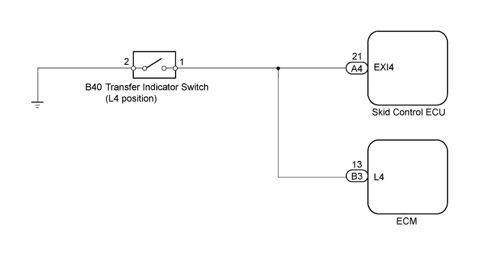

INSPECTION PROCEDURE
- NOTICE:
- When replacing the master cylinder solenoid, perform zero point calibration (Click here).
| 1. INSPECT SKID CONTROL ECU (EXI4 TERMINAL VOLTAGE) |

Disconnect the skid control ECU connector.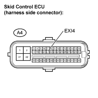
Turn the ignition switch to ON.
Measure the voltage.
- Standard voltage:
Tester Connection
Transfer Condition
Specified Condition
A4-21 (EXI4) - Body ground
L4
Below 1.5 V
A4-21 (EXI4) - Body ground
Other than above
8 to 14 V
|
|
||||

| OK | |
 |
| 2. PERFORM TEST MODE INSPECTION (SIGNAL CHECK) |
Check if the test mode DTC (C1283/83) is detected.
- Result:
Result
Proceed to
Test mode DTC (C1283/83) not output
A
Test mode DTC (C1283/83) output
B
|
|
||||

| A | |
|
| 3. RECONFIRM DTC |
Clear the DTC (Click here).
Check if the same DTC is recorded (Click here).
- Result:
Result
Proceed to
DTC output
A
DTC not output
B
|
|
||||
| A | ||
 |
||
| ||
| 4. INSPECT TRANSFER INDICATOR SWITCH (for L4 POSITION) |
Disconnect the transfer indicator switch (for L4 position) connector.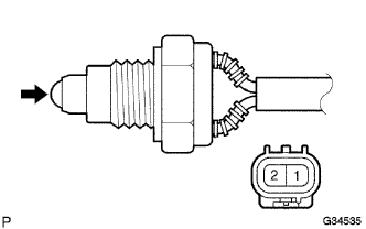
Remove the transfer indicator switch (for L4 position).
Measure the resistance.
- Standard resistance:
Tester Connection
Switch Position
Specified Condition
1 - 2
Pushed
Below 1 Ω
1 - 2
Free
10 kΩ or higher
|
|
||||
| OK | |
|
| 5. CHECK HARNESS AND CONNECTOR (SKID CONTROL ECU - TRANSFER INDICATOR SWITCH) |
Disconnect the skid control ECU connector.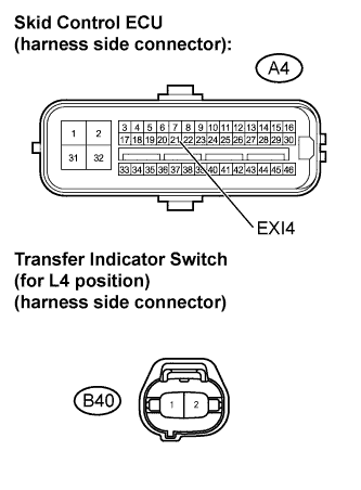
Disconnect the transfer indicator switch (for L4 position) connector.
Measure the resistance.
- Standard resistance:
Tester Connection
Specified Condition
A4-21 (EXI4) - B40-1
Below 1 Ω
A4-21 (EXI4) - Body ground
10 kΩ or higher
|
|
||||
| OK | |
|
| 6. CHECK HARNESS AND CONNECTOR (SKID CONTROL ECU - ECM) |
Disconnect the skid control ECU connector.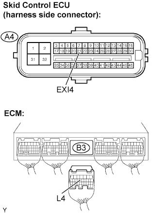
Disconnect the ECM connector.
Measure the resistance.
- Standard resistance:
Tester Connection
Specified Condition
A4-21 (EXI4) - B3-13 (L4)
Below 1 Ω
A4-21 (EXI4) - Body ground
10 kΩ or higher
B3-13 (L4) - Body ground
10 kΩ or higher
|
|
||||
| OK | ||
|
||
| ||