C1268 Transfer L4 Position Switch Circuit
Diagnostic trouble codes · Vehicles built from Aug 2012
Also covers:
- C1283 L4 Position Switch
Versions by build date: Nov 2010 – Jul 2012 from Aug 2012
DESCRIPTION
A-TRC is activated if wheel skid is detected while the transfer is in the L4 (for automatic transmission) or LL (for manual transmission) position.| DTC Code |
DTC Detection Condition |
Trouble Area |
| C1268 |
|
|
| C1283 |
Detected only during test mode |
|
- *1: w/ Rear Differential Lock
- *2: w/o Rear Differential Lock
- *3: for Manual Transmission
WIRING DIAGRAM
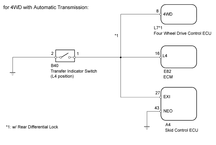

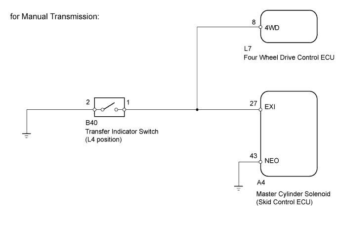
INSPECTION PROCEDURE
- NOTICE:
- When replacing the master cylinder solenoid, perform zero point calibration (Click here).
| 1. CHECK HARNESS AND CONNECTOR (NEO TERMINAL) |

Disconnect the A4 skid control ECU connector.
Measure the resistance according to the value(s) in the table below.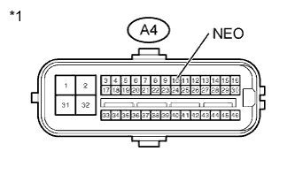
- Standard Resistance:
Tester Connection
Condition
Specified Condition
A4-10 (NEO) - Body ground
Always
Below 1 Ω
Text in Illustration *1
Front view of wire harness connector
(to Skid Control ECU)
|
|
||||

| OK | |
 |
| 2. INSPECT SKID CONTROL ECU (EXI TERMINAL VOLTAGE) |
for Automatic Transmission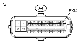
Disconnect the A4 skid control ECU connector.
Turn the ignition switch to ON.
Measure the voltage according to the value(s) in the table below.
- Standard Voltage:
Tester Connection
Transfer Condition
Specified Condition
A4-27 (EXI) - Body ground
L4
Below 1.5 V
A4-27 (EXI) - Body ground
Other than above
8 to 14 V
Text in Illustration *a
Front view of wire harness connector
(to Skid Control ECU)
for Manual Transmission
Disconnect the A4 skid control ECU connector.
Turn the ignition switch to ON.
Measure the voltage according to the value(s) in the table below.
- Standard Voltage:
Tester Connection
Transfer Condition
Specified Condition
A4-27 (EXI) - Body ground
LL
Below 1.5 V
A4-27 (EXI) - Body ground
Other than above
8 to 14 V
Text in Illustration *a
Front view of wire harness connector
(to Skid Control ECU)
Result Result
Proceed to
OK
A
NG (for Automatic Transmission w/ Rear Diff Lock)
B
NG (for Automatic Transmission w/o Rear Diff Lock)
C
NG (for Manual Transmission w/ Rear Diff Lock)
D
|
|
||||
|
|
||||
|
|
||||

| A | |
|
| 3. RECONFIRM DTC |
Clear the DTC (Click here).
Check if the same DTC is recorded (Click here).
Result Result
Proceed to
DTC output
A
DTC not output
B
|
|
||||
| A | ||
 |
||
| ||
| 4. CHECK HARNESS AND CONNECTOR (SKID CONTROL ECU - ECM, FOUR WHEEL DRIVE CONTROL ECU) |
Disconnect the A4 skid control ECU connector.
Disconnect the transfer indicator switch (for L4 position) connector.
Disconnect the ECM connector.
Disconnect the four wheel drive control ECU connector.
Measure the resistance according to the value(s) in the table below.
- Standard Resistance:
Tester Connection
Condition
Specified Condition
A4-27 (EXI) - E82-16 (L4)
Always
Below 1 Ω
A4-27 (EXI) - L7-8 (4WD)
Always
Below 1 Ω
Result Result
Proceed to
NG
A
OK
B
|
|
||||
| A | ||
|
||
| ||
| 5. CHECK HARNESS AND CONNECTOR (SKID CONTROL ECU - ECM) |
Disconnect the A4 skid control ECU connector.
Disconnect the transfer indicator switch (for L4 position) connector.
Disconnect the ECM connector.
Measure the resistance according to the value(s) in the table below.
- Standard Resistance:
Tester Connection
Condition
Specified Condition
A4-27 (EXI) - E82-16 (L4)
Always
Below 1 Ω
Result Result
Proceed to
NG
A
OK
B
|
|
||||
| A | ||
|
||
| ||
| 6. CHECK HARNESS AND CONNECTOR (SKID CONTROL ECU - FOUR WHEEL DRIVE CONTROL ECU) |
Disconnect the A4 skid control ECU connector.
Disconnect the transfer indicator switch (for L4 position) connector.
Disconnect the four wheel drive control ECU connector.
Measure the resistance according to the value(s) in the table below.
- Standard Resistance:
Tester Connection
Condition
Specified Condition
A4-27 (EXI) - L7-8 (4WD)
Always
Below 1 Ω
Result Result
Proceed to
NG
A
OK
B
|
|
||||
| A | ||
|
||
| ||
| 7. REPLACE 4 WHEEL DRIVE CONTROL ECU |
Replace the four wheel drive control ECU.
Clear the DTCs.
Check if the same DTC is recorded.
Result Result
Proceed to
DTC not output
A
DTC output
B
|
|
||||
| A | ||
|
||
| ||
| 8. REPLACE ECM |
Replace the ECM (Click here).
Clear the DTCs.
Check if the same DTC is recorded.
Result Result
Proceed to
DTC not output
A
DTC output
B
|
|
||||
| A | ||
|
||
| ||