C1258/58 Transfer 4WD Position Switch Circuit
Diagnostic trouble codes · Vehicles built Jul 2007 – Jul 2008
Also covers:
- C1282/82 Center Differential Lock Position Switch Malfunction (Test Mode DTC)
DESCRIPTION
This circuit monitors whether the transfer is in 2WD or 4WD mode and inputs the signal to the skid control ECU.In 2WD mode, TRC is activated.
In 4WD mode, A-TRAC is activated.
| DTC No. |
DTC Detecting Conditions |
Trouble Areas |
| C1258/58 |
|
|
| C1282/82 |
Detected only during test mode |
|
WIRING DIAGRAM
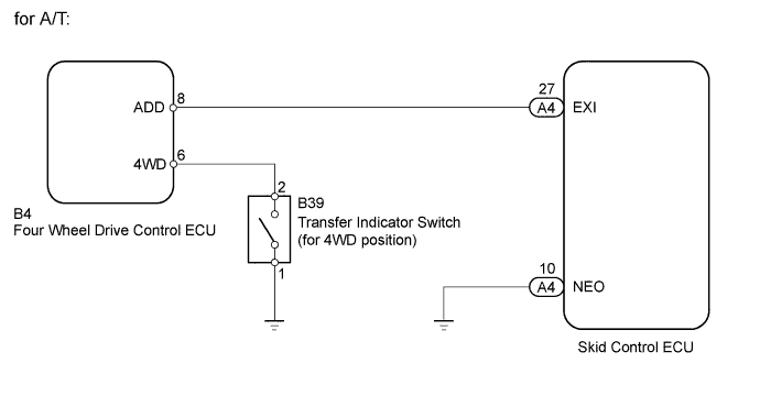

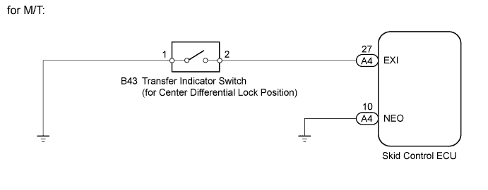
INSPECTION PROCEDURE
- NOTICE:
- When replacing the master cylinder solenoid, perform zero point calibration (Click here).
| 1. INSPECT SKID CONTROL ECU TERMINAL VOLTAGE (EXI) |

Disconnect the skid control ECU connector.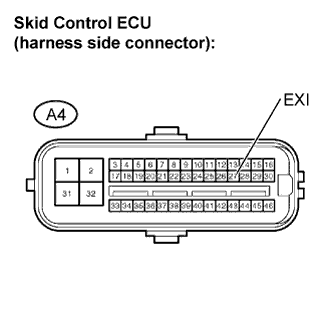
Turn the ignition switch to ON.
A/T:
Move the transfer high and low shift lever to the H2, H4, and L4 ranges, and measure the voltages in each range.
- Standard voltage:
Tester Connection
Transfer Range
Specified Condition
A4-27 (EXI) - Body ground
H2
8 to 14 V
A4-27 (EXI) - Body ground
H4, L4
Below 1.5 V
M/T:
Move the transfer high and low shift lever to the H, HL, and LL ranges, and measure the voltages in each range.
- Standard voltage:
Tester Connection
Transfer Range
Specified Condition
A4-27 (EXI) - Body ground
H
8 to 14 V
A4-27 (EXI) - Body ground
HL, LL
Below 1.5 V
- Result:
Result
Proceed to
OK
A
NG (A/T)
B
NG (M/T)
C
|
|
||||
|
|
||||

| A | |
 |
| 2. CHECK HARNESS AND CONNECTOR (NEO TERMINAL - BODY GROUND) |
Disconnect the skid control ECU connector.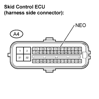
Measure the resistance.
- Standard resistance:
Tester Connection
Vehicle Drive Train
Specified Condition
A4-10 (NEO) - Body ground
4WD
Below 1 Ω
|
|
||||

| OK | |
|
| 3. RECONFIRM DTC |
Clear the DTC (Click here).
Check if the same DTC is recorded (Click here).
- Result:
Result
Proceed to
DTC output
A
DTC not output
B
|
|
||||
| A | ||
 |
||
| ||
| 4. INSPECT TRANSFER INDICATOR SWITCH (for 4WD position) |
Disconnect the transfer indicator switch (4WD position) connector.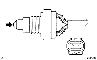
Remove the transfer indicator switch (4WD position).
Measure the resistance.
- Standard resistance:
Tester Connection
Switch Position
Specified Condition
1 - 2
Pushed
Below 1 Ω
1 - 2
Released
10 kΩ or higher
|
|
||||
| OK | |
|
| 5. CHECK HARNESS AND CONNECTOR (FOUR WHEEL DRIVE CONTROL ECU - TRANSFER INDICATOR SWITCH) |
Disconnect the four wheel drive control ECU connector.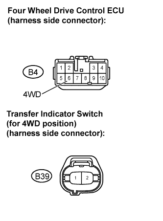
Disconnect the transfer indicator switch (for 4WD position) connector.
Measure the resistance.
- Standard resistance:
Tester Connection
Specified Condition
B4-6 (4WD) - B39-2
Below 1 Ω
B4-6 (4WD) - Body ground
10 kΩ or higher
|
|
||||
| OK | |
|
| 6. CHECK HARNESS AND CONNECTOR (SKID CONTROL ECU - FOUR WHEEL DRIVE CONTROL ECU) |
Disconnect the skid control ECU connector.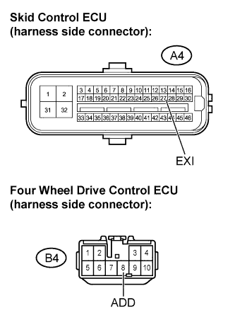
Disconnect the 4WD control ECU connector.
Measure the resistance.
- Standard resistance:
Tester Connection
Specified Condition
A4-27 (EXI) - B4-8 (ADD)
Below 1 Ω
A4-27 (EXI) - Body ground
10 kΩ or higher
|
|
||||
| OK | |
|
| 7. REPLACE 4 WHEEL DRIVE CONTROL ECU NO.2 |
Replace the four wheel drive control ECU.
| NEXT | |
|
| 8. RECONFIRM DTC |
Clear the DTC (Click here).
Check if the same DTC is recorded (Click here).
- Result:
Result
Proceed to
DTC output
A
DTC not output
B
|
|
||||
| A | ||
|
||
| ||
| 9. INSPECT TRANSFER INDICATOR SWITCH (for CENTER DIFFERENTIAL LOCK POSITION) |
Disconnect the transfer indicator switch (center differential lock position) connector.
Remove the transfer indicator switch (center differential lock position).
Measure the resistance.
- Standard resistance:
Tester Connection
Switch Position
Specified Condition
1 - 2
Pushed
Below 1 Ω
1 - 2
Released
10 kΩ or higher
|
|
||||
| OK | |
|
| 10. CHECK HARNESS AND CONNECTOR (SKID CONTROL ECU - TRANSFER INDICATOR SWITCH) |
Disconnect the skid control ECU connector.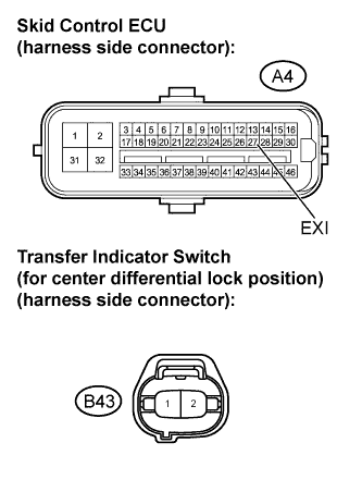
Disconnect the transfer indicator switch (center differential lock position) connector.
Measure the resistance.
- Standard resistance:
Tester Connection
Specified Condition
A4-27 (EXI) - B43-2
Below 1 Ω
A4-27 (EXI) - Body ground
10 kΩ or higher
|
|
||||
| OK | |
|
| 11. RECONFIRM DTC |
Clear the DTC (Click here).
Check if the same DTC is recorded (Click here).
- Result:
Result
Proceed to
DTC output
A
DTC not output
B
|
|
||||
| A | ||
|
||
| ||