Front Fog Light Circuit
Circuit diagnosis · Vehicles built from Aug 2014
DESCRIPTION
The front fog light illuminates only when the headlight dimmer switch is in the HEAD or TAIL position. When the switch is turned to OFF, the front fog light turns off automatically.WIRING DIAGRAM
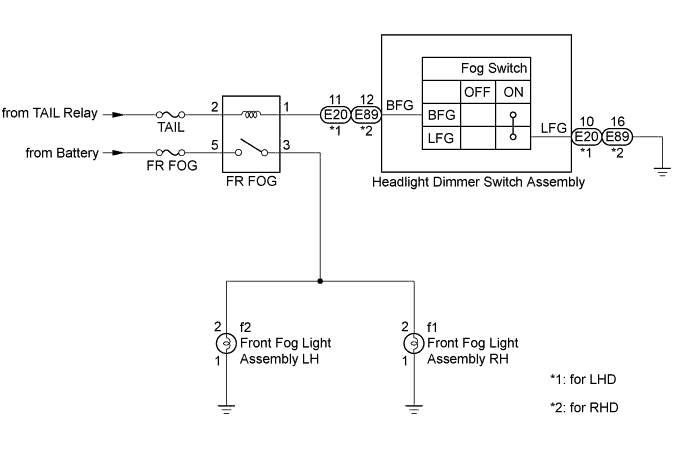

INSPECTION PROCEDURE
- NOTICE:
- Inspect the fuses and bulbs for circuits related to this system before performing the following inspection procedure.
| 1. CHECK VEHICLE CONDITION |

Check whether the front fog lights illuminate.
Result Result
Proceed to
Neither left nor right front fog light illuminates
A
Either left or right front fog light illuminates
B
|
|
||||

| A | |
 |
| 2. CHECK HARNESS AND CONNECTOR (FR FOG RELAY - POWER SOURCE) |
Remove the FR FOG relay from the No. 2 engine room relay block.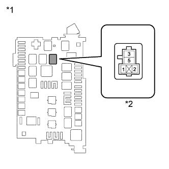
Measure the voltage according to the value(s) in the table below.
- Standard Voltage:
Tester Connection
Condition
Specified Condition
FR FOG-2 - Body ground
Always
11 to 14 V
FR FOG-5 - Body ground
Always
11 to 14 V
Text in Illustration *1
No. 2 Engine Room Relay Block
*2
FR FOG Relay Holder
|
|
||||

| OK | |
|
| 3. CHECK HARNESS AND CONNECTOR (FR FOG RELAY - HEADLIGHT DIMMER SWITCH ASSEMBLY) |
Remove the FR FOG relay from the No. 2 engine room relay block.
Disconnect the E20*1 or E89*2 headlight dimmer switch assembly connector.
Measure the resistance according to the value(s) in the table below.
- *1: for LHD
- *2: for RHD
- Standard Resistance:
for LHD Tester Connection
Condition
Specified Condition
FR FOG-1 - E20-11(BFG)
Always
Below 1 Ω
FR FOG-1 or E20-11(BFG) - Body ground
Always
10 kΩ or higher
- Standard Resistance:
for RHD Tester Connection
Condition
Specified Condition
FR FOG-1 - E89-12(BFG)
Always
Below 1 Ω
FR FOG-1 or E20-11(BFG) - Body ground
Always
10 kΩ or higher
- *1: for LHD
|
|
||||
| OK | |
|
| 4. INSPECT HEADLIGHT DIMMER SWITCH ASSEMBLY |
Remove the headlight dimmer switch assembly (Click here).
Inspect the headlight dimmer switch assembly (Click here).
|
|
||||
| OK | |
|
| 5. CHECK HARNESS AND CONNECTOR (FRONT FOG LIGHT ASSEMBLY - FR FOG RELAY AND BODY GROUND) |
Disconnect the f2 and f1 front fog light assembly connectors.
Remove the FR FOG relay from the No. 2 engine room relay block.
Measure the resistance according to the value(s) in the table below.
- Standard Resistance:
Tester Connection
Switch Condition
Specified Condition
FR FOG-3 - f2-2
Always
Below 1 Ω
FR FOG-3 or f2-2 - Body ground
Always
10 kΩ or higher
f2-1 - Body ground
Always
Below 1 Ω
FR FOG-3 - f1-2
Always
Below 1 Ω
FR FOG-3 - f1-2 - Body ground
Always
10 kΩ or higher
f1-1 - Body ground
Always
Below 1 Ω
Reconnect the front fog light assembly connectors.
|
|
||||
| OK | ||
 |
||
| ||