All Doors cannot be Locked / Unlocked Simultaneously
Circuit diagnosis · Vehicles built Jul 2007 – Oct 2010
Versions by build date: Jul 2007 – Oct 2010 Nov 2010 – Jul 2011 from Aug 2011
DESCRIPTION
The main body ECU receives switch signals from the door control switch on the power window regulator master switch, door control switch, driver side door key cylinder, passenger side door key cylinder and back door key cylinder, and activates the door lock motor on each door accordingly.WIRING DIAGRAM
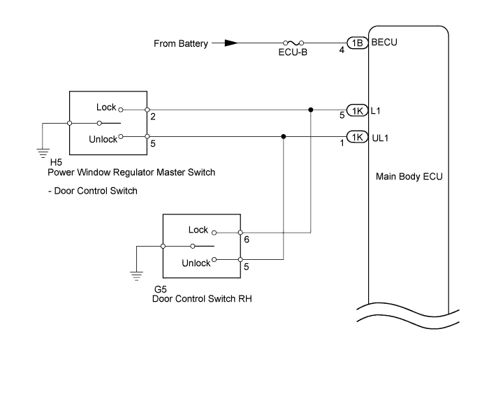

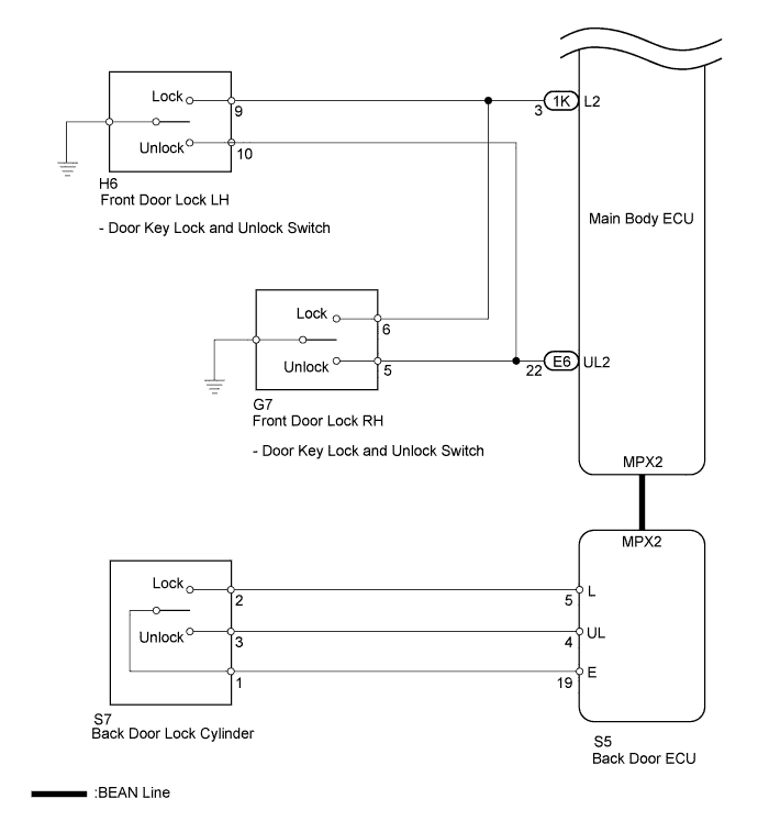
INSPECTION PROCEDURE
| 1. PERFORM ACTIVE TEST USING INTELLIGENT TESTER (DOOR LOCK) |

Connect a intelligent tester to the DLC3.
Turn the ignition switch to ON.
Turn the tester ON.
Enter the following menus: Body Electrical / Main Body / Active Test.
According to the display on tester, perform the "Active Test".
- Main Body:
Tester Display
Test Part
Control Range
Diagnostic Note
Door Lock
Operate door lock motor
LOCK or UNLOCK
-
- Result:
Symptom
Proceed to
Doors can be locked / Unlocked
A
Doors cannot be locked / Unlocked
B
|
|
||||

| B | |
 |
| 2. INSPECT FUSE (ECU-B) |
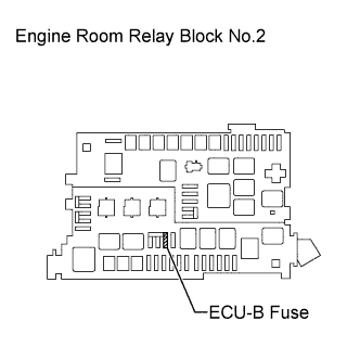 |
Remove the ECU-B fuse from the engine room R/B No.2.
Measure the resistance.
- Standard resistance:
- Below 1 Ω
Reinstall the ECU-B fuse.
|
|
||||

| OK | |
|
| 3. CHECK HARNESS AND CONNECTOR (MAIN BODY ECU - BATTERY, BODY GROUND) |
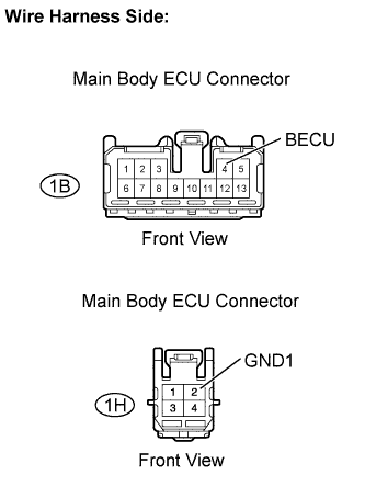 |
Disconnect the 1B and 1H main body ECU connectors.
Measure the voltage.
- Standard voltage:
Tester Connection
Specified Condition
IB-4 (BECU) - Body ground
11 to 14 V
Measure the resistance.
- Standard resistance:
Tester Connection
Specified Condition
IH-2 (GND1) - Body ground
Below 1 Ω
Reconnect the main body ECU connectors.
|
|
||||
| OK | ||
 |
||
| ||
| 4. CHECK OPERATION (ALL DOORS LOCK/ UNLOCK) |
All doors can be locked/unlocked at once using the following:
- Door control switch on the power window regulator master switch (switch operation)
- Door control switch on the front passenger side (switch operation).
- Door key cylinder linked with door lock on the driver side (key operation)
- Door key cylinder linked with door lock on the passenger side (key operation)
- Door key cylinder linked with door lock on the back door (key operation)
- Door control switch on the power window regulator master switch (switch operation)
Proceed to the next step according to the symptom if all the doors cannot be locked / unlocked at once.
- Result:
Symptom
Proceed to
All doors cannot be locked / unlocked at once using door control switch.
A
All doors cannot be locked / unlocked at once using door key cylinder
B
|
|
||||
| A | |
|
| 5. CHECK OPERATION (DOOR CONTROL SWITCH) |
Proceed to the next step according to the symptom listed in the table below.
- Result:
Symptom
Proceed to
All doors cannot be locked / unlocked at once using door control switch on power window regulator master switch
A
All doors cannot be locked / unlocked at once using door control switch on front passenger side
B
|
|
||||
| A | |
|
| 6. READ VALUE USING INTELLIGENT TESTER (DOOR CONTROL SWITCH) |
Connect a intelligent tester to the DLC3.
Turn the ignition switch to ON.
Turn the tester ON.
Enter the following menus: Body Electrical / Main Body / Data List.
According to the display on tester, read on the "Data List".
- Main Body:
Tester Display
Measurement Item/Range
Normal Condition
Diagnostic Note
Door Lock SW-Lock
Door manual lock switch signal / ON or OFF
ON: Door control switch on power window regulator master switch is pushed to lock position
OFF: Door control switch on power window regulator master switch is not pushed
-
Door Lock SW-Unlock
Door manual unlock switch signal / ON or OFF
ON: Door control switch on power window regulator master switch is pushed to unlock position
OFF: Door control switch on power window regulator master switch is not pushed
-
- OK:
- When the switch is operated, the intelligent tester displays ON and OFF as shown in the table.
|
|
||||
| NG | |
|
| 7. INSPECT POWER WINDOW REGULATOR MASTER SWITCH (DOOR CONTROL SWITCH) |
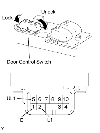 |
Remove the power window regulator master switch (door control switch).
Measure the resistance
- Standard resistance:
Tester Connection
Switch Condition
Specified Condition
1 (E) - 2 (L1)
Locked
Below 1 Ω
1 (E) - 2 (L1)
OFF
10 kΩ or higher
1 (E) - 5 (UL1)
OFF
10 kΩ or higher
1 (E) - 5 (UL1)
Unlocked
Below 1 Ω
Reinstall the power window regulator master switch.
|
|
||||
| OK | |
|
| 8. CHECK HARNESS AND CONNECTOR (DOOR CONTROL SWITCH - MAIN BODY ECU, BODY GROUND) |
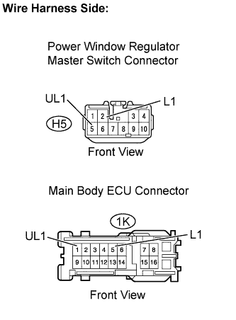 |
Disconnect the 1K main body ECU connector.
Disconnect the H5 power window regulator master switch (door control switch) connector.
Measure the resistance of the wire harness side connectors.
- Standard resistance:
Tester Connection
Specified Condition
H5-2 (L1) - 1K-5 (L1)
Below 1 Ω
H5-5 (UL1) - 1K-1 (UL1)
Below 1 Ω
H5-2 (L1) or 1K-5 (L1) - Body ground
10 kΩ or higher
H5-5 (UL1) or 1K-1 (UL1) - Body ground
10 kΩ or higher
Reconnect the main body ECU connector.
Reconnect the the power window regulator master switch connector.
|
|
||||
| OK | ||
|
||
| ||
| 9. READ VALUE USING INTELLIGENT TESTER (DOOR CONTROL SWITCH) |
Connect a intelligent tester to the DLC3.
Turn the ignition switch to ON.
Turn the tester on.
Enter the following menus: Body Electrical / Main Body / Data List.
According to the display on tester, read on the "Data List".
- Main Body:
Tester Display
Measurement Item/Range
Normal Condition
Diagnostic Note
Door Lock SW-Lock
Door manual lock switch signal / ON or OFF
ON: Passenger side door control switch is pushed to lock position
OFF: Passenger side door control switch is not pushed
-
Door Lock SW-Unlock
Door manual unlock switch signal / ON or OFF
ON: Passenger side door control switch is pushed to unlock position
OFF: Passenger side door control switch is not pushed
-
- OK:
- When the door key cylinder is operated, the intelligent tester displays ON and OFF as shown in the table.
|
|
||||
| NG | |
|
| 10. INSPECT DOOR CONTROL SWITCH RH |
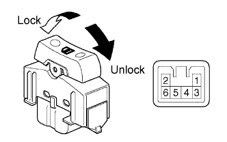 |
Remove the door control switch RH.
Measure the resistance
- Standard resistance:
Tester Connection
Switch Condition
Specified Condition
3 - 6
Locked
Below 1 Ω
3 - 6
OFF
10 kΩ or higher
3 - 5
OFF
10 kΩ or higher
3 - 5
Unlocked
Below 1 Ω
Reinstall the door control switch.
|
|
||||
| OK | |
|
| 11. CHECK HARNESS AND CONNECTOR (DOOR CONTROL SWITCH - MAIN BODY ECU, BODY GROUND) |
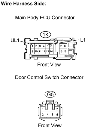 |
Disconnect the 1K main body ECU connector.
Disconnect the G5 door control switch RH connector.
Measure the resistance of the wire harness side connectors.
- Standard resistance:
Tester Connection
Specified Condition
G5-6 - 1K-5 (L1)
Below 1 Ω
G5-5 - 1K-1 (UL1)
Below 1 Ω
G5-6 or 1K-5 (L1) - Body ground
10 kΩ or higher
G5-5 or 1K-1 (UL1) - Body ground
10 kΩ or higher
Reconnect the main body ECU connector.
Reconnect the the door control switch RH connector.
|
|
||||
| OK | ||
|
||
| ||
| 12. CHECK OPERATION (DOOR KEY CYLINDER) |
Proceed to the next step according to the symptom listed in the table below.
- Result:
Symptom
Proceed to
All doors cannot be locked / unlocked at once using door key cylinder on driver side
A
All doors cannot be locked / unlocked at once using door key cylinder on front passenger side
B
All doors cannot be locked / unlocked at once using door key cylinder on back door
C
|
|
||||
|
|
||||
| A | |
|
| 13. READ VALUE USING INTELLIGENT TESTER (DOOR KEY SWITCH) |
Connect a intelligent tester to the DLC3.
Turn the ignition switch to ON.
Turn the tester ON.
Enter the following menus: Body Electrical / Main Body / Data List.
According to the display on tester, read on the "Data List".
- Main Body:
Tester Display
Measurement Item/Range
Normal Condition
Diagnostic Note
Door Key SW-Lock
Door key linked lock switch signal / ON or OFF
ON: Driver side door key cylinder is turned to lock position
OFF: Driver side door key cylinder is not turned
-
Door Key SW-Unlock
Door key linked unlock switch signal / ON or OFF
ON: Driver side door key cylinder is turned to unlock position
OFF: Driver side door key cylinder is not turned
-
- OK:
- When the switch is operating, the intelligent tester should display as shown in the table.
|
|
||||
| NG | |
|
| 14. INSPECT FRONT DOOR LOCK LH |
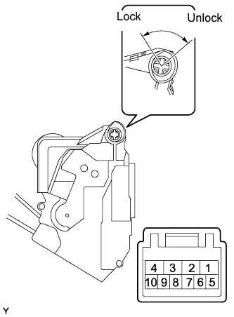 |
Remove the front door lock LH.
Measure the resistance of the door lock and unlock switch.
- Standard resistance:
Tester Connection
Door Lock Condition
Specified Condition
7 - 9
Locked
Below 1 Ω
7 - 9
Unlocked
10 kΩ or higher
7 - 10
Locked
10 kΩ or higher
7 - 10
Unlocked
Below 1 Ω
Reinstall the front door lock LH.
|
|
||||
| OK | |
|
| 15. CHECK HARNESS AND CONNECTOR (FRONT DOOR LOCK LH - MAIN BODY ECU) |
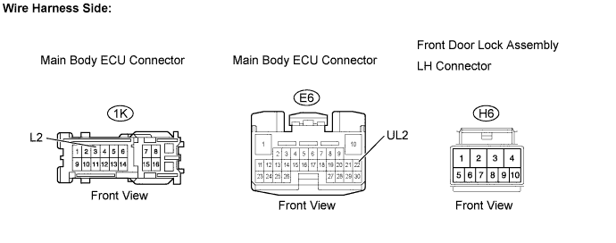
Disconnect the 1K and E6 main body ECU connectors.
Disconnect the H6 front door lock LH connector.
Measure the resistance.
- Standard resistance:
Tester Connection
Specified Condition
H6-9 - 1K-3 (L2)
Below 1 Ω
H6-10 - E6-22 (UL2)
Below 1 Ω
H6-9 or 1K-3 (L2) - Body ground
10 kΩ or higher
H6-10 or E6-22 (UL2) - Body ground
10 kΩ or higher
Reconnect the main body ECU connectors.
Reconnect the front door lock LH connector.
|
|
||||
| OK | ||
|
||
| ||
| 16. READ VALUE USING INTELLIGENT TESTER (DOOR KEY SWITCH) |
Connect a intelligent tester to the DLC3.
Turn the ignition switch to ON.
Turn the tester ON.
Enter the following menus: Body Electrical / Main Body / Data List.
According to the display on tester, read on the "Data List".
- Main Body:
Tester Display
Measurement Item/Range
Normal Condition
Diagnostic Note
Door Key SW-Lock
Door key linked lock switch signal / ON or OFF
ON: Front passenger side door key cylinder is turned to lock position
OFF: Front passenger side door key cylinder is not turned
-
Door Key SW-Unlock
Door key linked unlock switch signal / ON or OFF
ON: Front passenger side door key cylinder is turned to unlock position
OFF: Front passenger side door key cylinder is not turned
-
- OK:
- When the door key cylinder is operated, the intelligent tester displays ON and OFF as shown in the table.
|
|
||||
| NG | |
|
| 17. INSPECT FRONT DOOR LOCK RH |
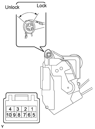 |
Remove the front door lock RH.
Measure the resistance of the door lock and unlock switch.
- Standard resistance:
Tester Connection
Door Lock Condition
Specified Condition
6 - 8
Locked
Below 1 Ω
6 - 8
Unlocked
10 kΩ or higher
5 - 8
Locked
10 kΩ or higher
5 - 8
Unlocked
Below 1 Ω
Reinstall the front door lock RH.
|
|
||||
| OK | |
|
| 18. CHECK HARNESS AND CONNECTOR (FRONT DOOR LOCK RH - MAIN BODY ECU) |
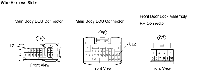
Disconnect the 1K and E6 main body ECU connectors.
Disconnect the G7 front door lock RH connector.
Measure the resistance.
- Standard resistance:
Tester Connection
Specified Condition
G7-6 - 1K-3 (L2)
Below 1 Ω
G7-5 - E6-22 (UL2)
Below 1 Ω
G7-6 or 1K-3 (L2) - Body ground
10 kΩ or higher
G7-5 or E6-22 (UL2) - Body ground
10 kΩ or higher
Reconnect the main body ECU connectors.
Reconnect the front door lock RH connector.
|
|
||||
| OK | ||
|
||
| ||
| 19. CHECK DTC OUTPUT |
Connect a intelligent tester to the DLC3.
Turn the ignition switch to ON.
Turn the tester ON.
Clear the DTCs (Click here).
Check whether DTC B1287 recurs 10 seconds or more after the ignition switch is turned on.
- OK:
- No DTC is output.
|
|
||||
| OK | |
|
| 20. INSPECT BACK DOOR LOCK CYLINDER |
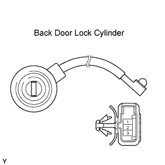 |
Remove the back door lock cylinder.
Measure the resistance of the the back door lock cylinder (door lock and unlock switch).
- Standard resistance:
Tester Connection
Key Condition
Specified Condition
2 - 1
Lock position
Below 1 Ω
2 - 1
Unlock position
10 kΩ or higher
3 - 1
Lock position
10 kΩ or higher
3 - 1
Unlock position
Below 1 Ω
Reinstall the the back door lock cylinder.
|
|
||||
| OK | |
|
| 21. CHECK HARNESS AND CONNECTOR (BACK DOOR LOCK CYLINDER - BACK DOOR ECU) |
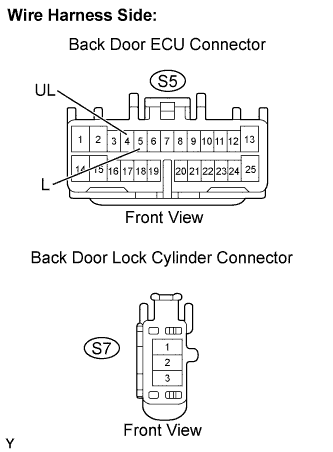 |
Disconnect the S5 back door ECU connector.
Disconnect the S7 back door lock cylinder connector.
Measure the resistance.
- Standard resistance:
Tester Connection
Specified Condition
S7-2 - S5-5 (L)
Below 1 Ω
S7-3 - S5-4 (UL)
Below 1 Ω
S7-2 or S5-5 (L) - Body ground
10 kΩ or higher
S7-3 or S5-4 (UL) - Body ground
10 kΩ or higher
Reconnect the back body ECU connector.
Reconnect the back door lock cylinder connector.
|
|
||||
| OK | ||
|
||
| ||