Home › ENGINE › 1GR-FE ENGINE CONTROL SYSTEM › SFI SYSTEM

DTC    P106B    Evaporative Emission System Pressure Sensor - Secondary Air Injection Pressure Sensor Correlation

for Preparation Click here


DESCRIPTION


DTC No.
DTC Detection Condition
Trouble Area
P106B
The pressure detected by the canister pressure sensor (Vapor Pressure Pump*) and the pressure detected by the pressure sensor of either emission control valve set (for bank 1 or bank 2) (Air Pump Pressure (Absolute)* or Air Pump2 Pressure (Absolute)*) differ by 6.98 kPa (52.35 mmHg) or more (2 trip detection logic).
  1. Canister pressure sensor (canister pump module)
  2. Emission control valve set (for bank 1)
  3. No. 2 emission control valve set (for bank 2)

HINT:
*: Name of Data List item


MONITOR DESCRIPTION

This DTC is stored when a deviation from pressure sensor characteristics is detected.
The pressure detected by the canister pressure sensor and the pressures detected by the pressure sensors of both emission control valve set (for bank 1 and bank 2) are checked 55 minutes after the ignition switch is turned off. If the pressure detected by the canister pressure sensor and the pressure detected by the pressure sensor of either emission control valve set (for bank 1 and bank 2) differ by a certain amount, the MIL is illuminated and a DTC is stored (2 trip detection logic).

HINT:
Correct judgment may not be possible when the elevation is 4000 m (13120 ft.) or more.


MONITOR STRATEGY


Related DTC
P106B: Evaporative emission system pressure sensor - secondary air injection system pressure sensor correlation
Required Sensors/Components (Main)
Canister pressure sensor
Pressure sensor (Emission control valve set)
Required Sensors/Components (Related)
-
Frequency of Operation
Once per driving cycle
Duration
Less than 65 seconds
MIL Operation
2 driving cycles
Sequence of Operation
None

TYPICAL ENABLING CONDITIONS


Monitor runs whenever following DTCs are not stored
P0452, P0453 (Evaporative emission system pressure sensor)
P2440 - P2445 (Secondary air injection system)
P2431 - P2433, P2436 - P2438 (Secondary air injection system pressure sensor)
Time elapsed after engine stop
50 minutes
Time after ECM started by soak-timer
60 seconds or more
Battery voltage
10.5 V or higher
Intake air temperature
-10°C (14°F) or higher
Engine coolant temperature
-10°C (14°F) or higher

TYPICAL MALFUNCTION THRESHOLDS


Difference between EVAP pressure and secondary air injection system pressure sensor (bank 1)
More than 6.98 kPa (52.35 mmHg)
Difference between EVAP pressure and secondary air injection system pressure sensor (bank 2)
More than 6.98 kPa (52.35 mmHg)

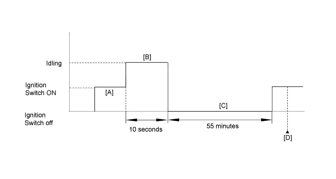
CONFIRMATION DRIVING PATTERN


A215924E04

  1. Connect the Techstream to the DLC3.
  2. Turn the ignition switch to ON and turn the Techstream on [A].
  3. Clear the DTCs (even if no DTCs are stored, perform the clear DTC procedure).
  4. Start the engine and idle it for 10 seconds [B].
  5. Turn the ignition switch off.
  6. Allow the vehicle to soak for 55 minutes [C].
  7. Turn the ignition switch to ON and turn the Techstream on.
  8. Enter the following menus: Powertrain / Engine and ECT / Trouble Codes [D].
  9. Read the pending DTCs.

    HINT:
    1. If a pending DTC is output, the system is malfunctioning.
    2. If a pending DTC is not output, perform the following procedure.

  10. Enter the following menus: Powertrain / Engine and ECT / Utility / All Readiness.
  11. Input the DTC: P106B.
  12. Check the DTC judgment result.

    Techstream Display
    Description
    NORMAL
    1. DTC judgment completed
    2. System normal
    ABNORMAL
    1. DTC judgment completed
    2. System abnormal
    INCOMPLETE
    1. DTC judgment not completed
    2. Perform driving pattern after confirming DTC enabling conditions
    N/A
    1. Unable to perform DTC judgment
    2. Number of DTCs which do not fulfill DTC preconditions has reached ECU memory limit

    HINT:
    If the judgment result shows ABNORMAL, the system has a malfunction.
    If the judgment result shows INCOMPLETE or N/A, perform steps [A] through [D] again.

  13. If the test result is INCOMPLETE or N/A and no pending DTC is output, perform a universal trip and check for permanent DTCs (Click here).

    HINT:
    1. If a permanent DTC is output, the system is malfunctioning.
    2. If no permanent DTC is output, the system is normal.


INSPECTION PROCEDURE

HINT:
  1. Read freeze frame data using the Techstream. Freeze frame data records the engine condition when malfunctions are detected. When troubleshooting, freeze frame data can help determine if the vehicle was moving or stationary, if the engine was warmed up or not, if the air-fuel ratio was lean or rich, and other data from the time the malfunction occurred.
  2. Refer to "Data List / Active Test" [Air Pump Pressure (Absolute), Air Pump 2 Pressure (Absolute) and Vapor Pressure Pump] (Click here).
  3. Bank 1 refers to the bank that includes the No. 1 cylinder*.
    *: The No. 1 cylinder is the cylinder which is farthest from the transmission.
  4. Bank 2 refers to the bank that does not include the No. 1 cylinder.

1.CHECK FOR ANY OTHER DTCS OUTPUT (IN ADDITION TO P106B)
  1. Connect the Techstream to the DLC3.

  1. Turn the ignition switch to ON.

  1. Turn the Techstream on.

  1. Enter the following menus: Powertrain / Engine and ECT / Trouble Codes.

  1. Read the DTCs.
    Result 
    Result
    Proceed to
    DTC P106B is output
    A
    DTC P106B and other DTCs are output
    B

    HINT:
    If any DTCs other than P106B are output, perform troubleshooting for those DTCs first.


B
GO TO DTC CHART (Click here)
A


2.READ VALUE USING TECHSTREAM (VAPOR PRESSURE PUMP, AIR PUMP PRESSURE (ABSOLUTE) AND AIR PUMP2 PRESSURE (ABSOLUTE))
  1. Connect the Techstream to the DLC3.

  1. Turn the ignition switch to ON.

  1. Turn the Techstream on.

  1. Enter the following menus: Powertrain / Engine and ECT / Data List / Vapor Pressure Pump, Air Pump Pressure (Absolute) and Air Pump2 Pressure (Absolute).

  1. Compare the Vapor Pressure Pump, Air Pump Pressure (Absolute) and Air Pump2 Pressure (Absolute) data from the Data List with the current atmospheric pressure*.

    HINT:
    1. *: Standard atmospheric pressure is 101 kPa (760 mmHg) at sea level. The atmospheric pressure decreases by approximately 1 kPa (7.5 mmHg) for every 100 m increase in elevation. Atmospheric pressure is also affected by weather conditions. Atmosphere Pressure listed in the Data List cannot be used as a reference for this check.
    2. If you do not know the atmospheric pressure, refer to the Vapor Pressure Pump value of other vehicles in the workshop and check the difference in pressure.


    Result 
    Result
    Proceed to
    The Vapor Pressure Pump value differs from the atmospheric pressure by 7.0 kPa (52.5 mmHg) or more
    A
    The Air Pump Pressure (Absolute) value differs from the atmospheric pressure by 7.0 kPa (52.5 mmHg) or more
    B
    The Air Pump2 Pressure (Absolute) value differs from the atmospheric pressure by 7.0 kPa (52.5 mmHg) or more
    C


B
Go to step 4

C
Go to step 5
A


3.REPLACE CANISTER
  1. Replace the canister (Click here).


NEXT
Go to step 6

4.REPLACE EMISSION CONTROL VALVE SET
  1. Replace the emission control valve set (Click here).


NEXT
Go to step 6

5.REPLACE NO. 2 EMISSION CONTROL VALVE SET
  1. Replace the No. 2 emission control valve set (Click here).


NEXT


6.CONFIRM WHETHER MALFUNCTION HAS BEEN SUCCESSFULLY REPAIRED
  1. Connect the Techstream to the DLC3.

  1. Turn the ignition switch to ON and turn the Techstream on.

  1. Clear the DTCs (Click here).

  1. Enter the following menus: Powertrain / Engine and ECT / Data List / Vapor Pressure Pump, Air Pump Pressure (absolute) and Air Pump2 Pressure (Absolute).

  1. Confirm that the difference between Vapor Pressure Pump and Air Pump Pressure (Absolute), and the difference between Vapor Pressure Pump and Air Pump2 Pressure (Absolute) are both 7.0 kPa (52.5 mmHg) or less.


NEXT

END