Engine Coolant Temperature Receiver Gauge Malfunction
Circuit diagnosis · Vehicles built Apr 2016 – Dec 2016
Versions by build date: Oct 2014 – Dec 2014 Jan 2015 – Mar 2016 Apr 2016 – Dec 2016 from Jan 2017
DESCRIPTION
The combination meter assembly receives engine coolant temperature signal from the ECM via the CAN communication line. The combination meter assembly displays an engine coolant temperature indication that is calculated based on the data received from the ECM.WIRING DIAGRAM
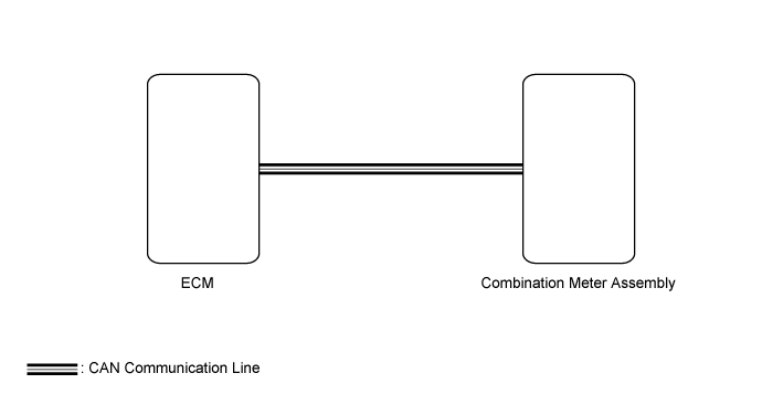

INSPECTION PROCEDURE
- NOTICE:
- Before starting following inspection, check if the SFI*1 or ECD*2 system troubleshooting.
- *1: for 1TR-FE, 2TR-FE
- *2: for 1KD-FTV, 2KD-FTV, 5L-E
- for 1TR-FE (w/ Dual VVT-i): Click here
- for 2TR-FE (w/ Secondary Air Injection System): Click here
- for 2TR-FE (w/o Secondary Air Injection System): Click here
- for 2TR-FE (w/ Dual VVT-i): Click here
- for 1KD-FTV (w/ DPF): Click here
- for 1KD-FTV (w/o DPF): Click here
- for 2KD-FTV: Click here
- for 5L-E: Click here
- The meter/gauge system uses the CAN communication system. First inspect the communication systems by following How to Proceed with Troubleshooting (Click here). Troubleshoot the meter/gauge system after confirming that the communication systems are functioning properly.
- Before starting following inspection, check if the SFI*1 or ECD*2 system troubleshooting.
| 1. CHECK FOR DTC (SFI SYSTEM*1 OR ECD SYSTEM*2) |

- *1: for 1TR-FE, 2TR-FE
- *2: for 1KD-FTV, 2KD-FTV, 5L-E
Clear the DTCs (Click here).
Check for DTCs (Click here).
- OK:
- SFI system*1 or ECD system*2 DTCs are not output.
Result Result
Proceed to
OK
A
NG (for 1TR-FE)
B
NG (for 2TR-FE)
NG (for 1KD-FTV)
C
NG (for 2KD-FTV)
NG (for 5L-E)
- HINT:
- *: Go to procedure;
- for 1TR-FE (w/ Dual VVT-i): Click here
- for 2TR-FE (w/ Secondary Air Injection System): Click here
- for 2TR-FE (w/o Secondary Air Injection System): Click here
- for 2TR-FE (w/ Dual VVT-i): Click here
- for 1KD-FTV (w/ DPF): Click here
- for 1KD-FTV (w/o DPF): Click here
- for 2KD-FTV: Click here
- for 5L-E: Click here
- for 1TR-FE (w/ Dual VVT-i): Click here
|
|
||||
|
|
||||

| A | |
 |
| 2. PERFORM ACTIVE TEST USING GTS (WATER TEMPERATURE METER OPERATION) |
Use the Active Test to check the operation of the engine coolant temperature receiver gauge (Click here).
Combination Meter Tester Display
Test Part
Control Range
Diagnostic Note
Water Temperature Meter Operation
Engine coolant temperature receiver gauge
OFF, Low, Normal or High
-
- OK:
- Engine coolant temperature receiver gauge is normal.
|
|
||||
| OK | |
|
| 3. READ VALUE USING GTS (COOLANT TEMPERATURE) |
Use the Data List to check if the engine coolant temperature receiver gauge is operating properly (Click here).
| Tester Display |
Measurement Item/Range |
Normal Condition |
Diagnostic Note |
| Coolant Temperature |
Engine coolant temperature / 0 to 127.5°C (0 to 261.5°F) |
After warming up: 75 to 100°C (167 to 212°F) |
- |
- OK:
- Coolant temperature displayed on the tester is between 75 to 100°C (167 to 212°F) after warming up.
|
|
||||
| OK | |
|
| 4. READ VALUE USING GTS (COOLANT TEMP, COOLANT TEMPERATURE) |
Use the Data List to check if the engine coolant temperature receiver gauge is operating properly (Click here).
| Tester Display |
Measurement Item/Range |
Normal Condition |
Diagnostic Note |
| Coolant Temp |
Engine coolant temperature / Min.: -40°C (-40°F), Max: 140°C (284°F) |
75 to 100°C (167 to 212°F): After warming up |
- |
| Tester Display |
Measurement Item/Range |
Normal Condition |
Diagnostic Note |
| Coolant Temperature |
Engine coolant temperature / 0 to 127.5°C (0 to 261.5°F) |
After warming up: 75 to 100°C (167 to 212°F) |
- |
- OK:
- The Data List values of the ECUs match.
- HINT:
- When the Data List values of the ECUs match, an internal malfunction of the combination meter assembly is suspected.
- *: Replacement procedure;
- for 1TR-FE: Click here
- for 2TR-FE (w/o Dual VVT-i): Click here
- for 2TR-FE (w/ Dual VVT-i): Click here
- for 1KD-FTV: Click here
- for 2KD-FTV: Click here
- for 5L-E: Click here
- When the Data List values of the ECUs match, an internal malfunction of the combination meter assembly is suspected.
|
|
||||
| OK | |
|
| 5. CHECK COMBINATION METER ASSEMBLY |
Temporarily replace the combination meter assembly with a new one or normally functioning one (Click here).
Check that the operation of engine coolant temperature receiver gauge returns to normal (Click here).
- OK:
- The operation of engine coolant temperature receiver gauge returns to normal
- HINT:
- *: Replacement procedure;
- for 1TR-FE: Click here
- for 2TR-FE (w/o Dual VVT-i): Click here
- for 2TR-FE (w/ Dual VVT-i): Click here
- for 1KD-FTV: Click here
- for 2KD-FTV: Click here
- for 5L-E: Click here
- for 1TR-FE: Click here
|
|
||||
| OK | ||
 |
||
| ||