CLUTCH CLUTCH STROKE SENSOR INSTALLATION
CAUTION / NOTICE / HINT
- HINT:
- ·
Use the same procedure for RHD and LHD vehicles.
·The procedure listed below is for LHD vehicles.
PROCEDURE

 89280
1.INSTALL CLUTCH PEDAL STROKE SENSOR ASSEMBLY
- NOTICE:
- ·
Do not drop the clutch pedal stroke sensor.
·If the clutch pedal stroke sensor has been dropped, replace the clutch pedal stroke sensor with a new one.
When installing a new clutch pedal stroke sensor:
- NOTICE:
-
Do not break the clutch pedal stroke sensor lever set pin before installing the clutch pedal stroke sensor with the 2 nuts.
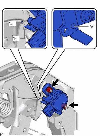
| *a | Clutch Pedal Stroke Sensor Lever |
| *b | Clutch Pedal Groove |
| *c | Clutch Pedal Stroke Sensor Lever Set Pin |
Install a new brake pedal stroke sensor assembly to the brake pedal support assembly with the 2 nuts.
- Torque:
- 8.5 N*m (87 kgf*cm, 75 in.*lbf)
- NOTICE:
- ·
Engage the sensor lever with the clutch pedal groove.
·Check that there is no foreign matter attached to the contact surface of the sensor.
·Check that the tip of the sensor lever is protruding from the clutch pedal groove.
Firmly depress the clutch pedal to break the clutch pedal stroke sensor lever set pin.
Remove the broken lever set pin.
When reusing the clutch pedal stroke sensor:
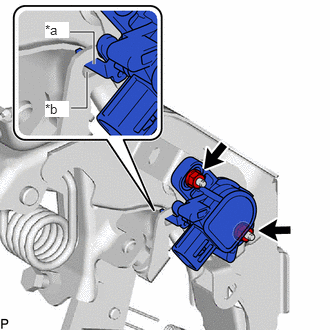
| *a | Clutch Pedal Stroke Sensor Lever |
| *b | Clutch Pedal Groove |
Install the clutch pedal stroke sensor assembly to the clutch pedal support assembly and temporarily tighten the 2 nuts.
- NOTICE:
- ·
Engage the clutch pedal stroke sensor lever with the clutch pedal groove.
·Check that there is no foreign matter attached to the contact surface of the clutch pedal stroke sensor.
·Check that the tip of the clutch pedal stroke sensor lever is protruding from the clutch pedal groove.
- HINT:
-
When fully tightening the nuts, perform Adjust Clutch Pedal Stroke Sensor Assembly first.
2.CONNECT WIRE HARNESS CONNECTOR
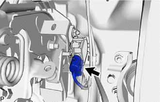
Connect the wire harness connector.
73900
3.INSTALL LOWER NO. 1 INSTRUMENT PANEL AIRBAG ASSEMBLY (w/ Driver Side Knee Airbag)
55313
4.INSTALL LOWER INSTRUMENT PANEL LH (w/o Driver Side Knee Airbag)
55445B
5.INSTALL INSTRUMENT PANEL FINISH PLATE (w/o Driver Side Knee Airbag)
55433B
6.INSTALL LOWER NO. 2 INSTRUMENT PANEL FINISH PANEL
55432D
7.INSTALL LOWER NO. 1 INSTRUMENT PANEL FINISH PANEL (for LHD)
55641
8.INSTALL NO. 1 INSTRUMENT PANEL UNDER COVER
55318C
9.INSTALL INSTRUMENT SIDE PANEL LH
55011A
10.INSTALL NO. 1 INSTRUMENT PANEL GARNISH SUB-ASSEMBLY (for LHD)
55631A
11.INSTALL NO. 1 INSTRUMENT PANEL UNDER TRAY STOPPER (for LHD)
62112
12.INSTALL COWL SIDE TRIM BOARD LH
67914B
13.INSTALL FRONT DOOR SCUFF PLATE LH
67912A
14.INSTALL FRONT DOOR OUTSIDE SCUFF PLATE LH
15.CONNECT CABLE TO NEGATIVE BATTERY TERMINAL
for 7GR-FKS: Click hereGeneral>MAINTENANCE>7GR-FKS BATTERY>INSTALLATION
for 1GD-FTV: Click hereGeneral>MAINTENANCE>1GD-FTV BATTERY>INSTALLATION
89280
16.ADJUST CLUTCH PEDAL STROKE SENSOR ASSEMBLY
- NOTICE:
-
When the clutch pedal stroke sensor is being reused, perform the following procedure to adjust it.
Connect the cable to the negative battery terminal.
Connect the GTS to the DLC3 with the ignition switch off.
Turn the ignition switch to on.
Turn the GTS on.
Enter the following menus: Powertrain / Engine / Data List / Clutch Stroke Sensor Voltage.
- Powertrain > Engine > Data List
-
Tester Display Clutch Stroke Sensor Voltage - 50003 372 607
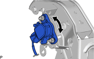
Read the stroke sensor value in the Data List, and turn the clutch pedal stroke sensor slowly to the right or left to adjust the output voltage so that it is within the following range.
- Standard Voltage (without the clutch pedal depressed):
0.96 to 1.04 V
Tighten the 2 nuts.
- Torque:
- 8.5 N*m (87 kgf*cm, 75 in.*lbf)
- NOTICE:
-
Do not depress the clutch pedal after turning the ignition switch to ON.
Turn the GTS off and turn the ignition switch off.
Disconnect the GTS from the DLC3.
Disconnect the cable to the negative battery terminal.
17. INITIALIZATION AFTER RECONNECTING BATTERY TERMINAL
Click hereGeneral>SETUP>WHEN DISCONNECTING OR RECONNECTING BATTERY TERMINAL>WORK PROCEDURE
- HINT:
-
When disconnecting and reconnecting the battery, there is an automatic learning function that completes learning when the respective system is used.
-
Click hereGeneral>SETUP>WHEN DISCONNECTING OR RECONNECTING BATTERY TERMINAL>AUTOMATIC LEARNING CHART
18.PERFORM DIAGNOSTIC SYSTEM CHECK
19.CHECK SRS WARNING LIGHT