SUPPLEMENTAL RESTRAINT SYSTEMS CENTER AIRBAG SENSOR ASSEMBLY REMOVAL
CAUTION / NOTICE / HINT
The necessary procedures (adjustment, calibration, initialization or registration) that must be performed after parts are removed and installed, or replaced during airbag sensor assembly removal/installation are shown below.
| Replaced Part or Performed Procedure | Necessary Procedure | Effect/Inoperative Function when Necessary Procedure not Performed | Link |
|---|---|---|---|
| Battery terminal is disconnected/reconnected | Memorize steering angle neutral point | Parking assist monitor system | ( ) |
| Airbag sensor assembly | w/ Stop and Start System:
·
Clear the zero point calibration data ·
Deceleration sensor zero point calibration |
Stop and start system | ()
|
| w/ VSC OFF Switch:
·
Perform reset memory ·
Perform acceleration sensor zero point calibration and store system information memorization |
·
VSC is disabled or malfunctions ·
DTCs are output ·
Slip indicator light illuminates ·
ABS warning light illuminates |
()
|
- HINT:
- ·
When the cable is disconnected/reconnected to the battery terminal, systems temporarily stop operating. However, each system has a function that completes learning the first time the system is used.
-Learning completes when vehicle is driven
Effect/Inoperative Function When Necessary Procedures are not Performed Necessary Procedures Link *: w/ Stop and start system
Stop and start system* Drive the vehicle until stop and start control is permitted (approximately 5 to 60 minutes). ( )
Lane control system Drive the vehicle straight ahead at 15 km/h (10 mph) or more for 1 second or more. ( )
Pre-collision system
-Learning completes when vehicle is operated normally
Effect/Inoperative Function When Necessary Procedures are not Performed Necessary Procedures Link Power slide door system Fully close the slide door by hand.
- HINT:
-
Initialization is not necessary if the above procedures are performed while the slide door is closed.
( )
Air conditioning system After the ignition switch is turned to ON, the servo motor standard position is recognized. -
·Use the same procedure for RHD and LHD vehicles.
·The procedure listed below is for LHD vehicles.
PROCEDURE

 1. PRECAUTION
- CAUTION:
-
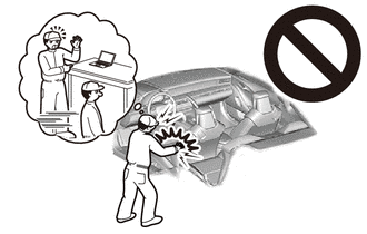
-
Be sure to read Precaution thoroughly before servicing.
- ·
for Type A:
Click hereVehicle Interior>SUPPLEMENTAL RESTRAINT SYSTEMS>AIRBAG SYSTEM (for Type A)>PRECAUTION
·for Type B:
Click hereVehicle Interior>SUPPLEMENTAL RESTRAINT SYSTEMS>AIRBAG SYSTEM (for Type B)>PRECAUTION
- NOTICE:
-
After the ignition switch is turned off, there may be a waiting time before disconnecting the negative (-) battery terminal.
-
Click hereGeneral>SETUP>WHEN DISCONNECTING OR RECONNECTING BATTERY TERMINAL>BEFORE DISCONNECTING BATTERY
2.DISCONNECT CABLE FROM NEGATIVE BATTERY TERMINAL
for 7GR-FKS:
for 1GD-FTV:
- CAUTION:
-
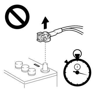
- ·
Wait at least 90 seconds after disconnecting the cable from the negative (-) battery terminal to disable the SRS system.
·If the airbag deploys for any reason, it may cause a serious accident.
67912A
3.REMOVE FRONT DOOR OUTSIDE SCUFF PLATE LH
67914B
4.REMOVE FRONT DOOR SCUFF PLATE LH
62112
5.REMOVE COWL SIDE TRIM BOARD LH
55631A
6.REMOVE NO. 1 INSTRUMENT PANEL UNDER TRAY STOPPER
55011A
7.REMOVE NO. 1 INSTRUMENT PANEL GARNISH SUB-ASSEMBLY
55318C
8.REMOVE INSTRUMENT SIDE PANEL LH
55641
9.REMOVE NO. 1 INSTRUMENT PANEL UNDER COVER
55642
10.REMOVE NO. 2 INSTRUMENT PANEL UNDER COVER
55632B
11.REMOVE NO. 2 INSTRUMENT PANEL UNDER TRAY SUPPORT
55012A
12.REMOVE NO. 2 INSTRUMENT PANEL GARNISH SUB-ASSEMBLY
55317A
13.REMOVE INSTRUMENT SIDE PANEL RH
55438A
14.REMOVE NO. 2 INSTRUMENT PANEL FINISH PANEL RETAINER
58903A
15.REMOVE CONSOLE REAR END PANEL SUB-ASSEMBLY (w/ Console Tray)
58919B
16.REMOVE CONSOLE BOX PLATE (w/ Console Tray, w/o Console BOX)
58839A
17.REMOVE CONSOLE BOX HOLE COVER (w/ Console Tray, w/o Console Box, w/o Fire Extinguisher)
58199D
18.REMOVE NO. 2 EXTINGUISHER BRACKET (w/ Console Tray, w/o Console Box, w/ Fire Extinguisher)
58825A
19.REMOVE CONSOLE BOX POCKET (w/ Console Tray, w/ Console Box)
58815A
20.REMOVE CONSOLE BOX CARPET (w/ Console Tray, w/ Console Box)
58820A
21.REMOVE CONSOLE COMPARTMENT BOX ASSEMBLY (w/ Console Tray, w/ Console Box)
58904B
22.REMOVE PARKING BRAKE HOLE COVER SUB-ASSEMBLY (w/ Console Tray, for Separate Seat Type)
58810J
23.REMOVE CONSOLE BOX ASSEMBLY (w/ Console Tray)
58534E
24.REMOVE CENTER FLOOR CARPET COVER LH
58533C
25.REMOVE CENTER FLOOR CARPET COVER RH
55646
26.REMOVE NO. 3 INSTRUMENT PANEL UNDER COVER
89170
27.REMOVE AIRBAG SENSOR ASSEMBLY
Check that the ignition switch is off.
Check that the cable is disconnected from the negative (-) battery terminal.
- CAUTION:
- ·
Wait at least 90 seconds after disconnecting the cable from the negative (-) battery terminal to disable the SRS system.
·If the airbag deploys for any reason, it may cause a serious accident.
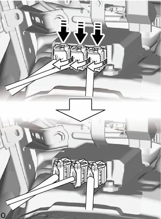

|
Push the Connector Lock |

|
Pull Out the Lock Lever |
Pull out the 3 connectors with its connector lock pushed to disconnect the 3 connectors.
- NOTICE:
-
When disconnecting any airbag connector, take care not to damage the airbag wire harness.
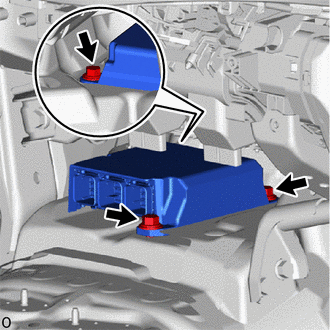
Remove the 3 bolts and airbag sensor assembly.
- NOTICE:
-
If the airbag sensor assembly has been dropped, or there are any cracks, dents or other defects in the case or connector, replace the airbag sensor assembly with a new one.