SUPPLEMENTAL RESTRAINT SYSTEMS SIDE AIRBAG SENSOR(for Center Pillar) INSTALLATION
CAUTION / NOTICE / HINT
- HINT:
- ·
Use the same procedure for RHD and LHD vehicles.
·The procedure listed below is for LHD vehicles.
·Use the same procedure for the RH and LH sides.
·The procedure listed below is for the LH side.
PROCEDURE

 89831A
1.INSTALL NO. 1 SIDE AIRBAG SENSOR
Check that the ignition switch is off.
Check that the cable is disconnected from the negative (-) battery terminal.
- CAUTION:
- ·
Wait at least 90 seconds after disconnecting the cable from the negative (-) battery terminal to disable the SRS system.
·If the airbag deploys for any reason, it may cause a serious accident.
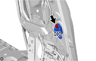
Attach the guide and hold the No. 1 side airbag sensor in place.
- NOTICE:
- ·
If the No. 1 side airbag sensor has been dropped, replace it with a new one.
·When installing the No. 1 side airbag sensor, be careful that the SRS wiring does not interfere with or is not pinched between other parts.
Install the bolt.
- Torque:
- 9.0 N*m (92 kgf*cm, 80 in.*lbf)
- NOTICE:
-
Tighten the bolt while holding the No. 1 side airbag sensor because the No. 1 side airbag sensor guide is easily damaged.
Check that there is no looseness in the installation parts of the No. 1 side airbag sensor.
Connect the airbag connector.
- NOTICE:
-
When connecting any airbag connector, take care not to damage the airbag wire harness.
- HINT:
-
Refer to How to Connect or Disconnect Airbag Connector:
- ·
62414A
2.INSTALL LOWER CENTER PILLAR GARNISH LH
Install the lower center pillar garnish LH.
- HINT:
-
Use the same procedure described for the RH side.
-
Click hereVehicle Interior>INTERIOR PANELS / TRIM>ROOF HEADLINING (for Full-trim)>INSTALLATION
Return the front door opening trim weatherstrip LH to its original position.
Click hereVehicle Exterior>DOOR / HATCH>FRONT DOOR OPENING TRIM WEATHERSTRIP>INSTALLATION
for Slide Door Side:
Return the No. 1 slide door weatherstrip LH to its original position.
- HINT:
-
Use the same procedure described for the RH side.
-
Click hereVehicle Exterior>DOOR / HATCH>REAR DOOR OPENING TRIM WEATHERSTRIP (except Wagon)>INSTALLATION
74680
3.INSTALL PILLAR ASSIST GRIP ASSEMBLY B (w/ Assist Grip)
74617A
4.INSTALL ASSIST GRIP PLUG (w/ Assist Grip)
73220
5.INSTALL FRONT SEAT OUTER BELT ASSEMBLY LH (FLOOR ANCHOR)
for Semi-trim:
Click hereVehicle Interior>SEAT BELT>FRONT SEAT OUTER BELT ASSEMBLY (for Semi-trim)>INSTALLATION
for Full-trim:
Click hereVehicle Interior>SEAT BELT>FRONT SEAT OUTER BELT ASSEMBLY (for Full-trim)>INSTALLATION
73233D
6.INSTALL OUTER LAP BELT ANCHOR COVER
for Semi-trim:
Click hereVehicle Interior>SEAT BELT>FRONT SEAT OUTER BELT ASSEMBLY (for Semi-trim)>INSTALLATION
for Full-trim:
Click hereVehicle Interior>SEAT BELT>FRONT SEAT OUTER BELT ASSEMBLY (for Full-trim)>INSTALLATION
67918D
7.INSTALL REAR DOOR SCUFF PLATE LH (for Slide Door Side)
- HINT:
-
Use the same procedure described for the RH side.
-
Click hereVehicle Interior>INTERIOR PANELS / TRIM>ROOF HEADLINING (for Semi-trim)>INSTALLATION
67914B
8.INSTALL FRONT DOOR SCUFF PLATE LH
67912A
9.INSTALL FRONT DOOR OUTSIDE SCUFF PLATE LH
10.CONNECT CABLE TO NEGATIVE BATTERY TERMINAL
for 7GR-FKS:
for 1GD-FTV:
11. INITIALIZATION AFTER RECONNECTING BATTERY TERMINAL
Click hereGeneral>SETUP>WHEN DISCONNECTING OR RECONNECTING BATTERY TERMINAL>WORK PROCEDURE
- HINT:
-
When disconnecting and reconnecting the battery, there is an automatic learning function that completes learning when the respective system is used.
-
Click hereGeneral>SETUP>WHEN DISCONNECTING OR RECONNECTING BATTERY TERMINAL>AUTOMATIC LEARNING CHART
12.PERFORM DIAGNOSTIC SYSTEM CHECK
13.CHECK SRS WARNING LIGHT
14.PERFORM SYSTEM INITIALIZATION AND CALIBRATION