1GD-FTV FUEL FUEL INJECTOR REMOVAL
CAUTION / NOTICE / HINT
The necessary procedures (adjustment, calibration, initialization, or registration) that must be performed after parts are removed, installed, or replaced during the injector assembly removal/installation are shown below.
| Replaced Part or Performed Procedure | Necessary Procedure | Effect/Inoperative Function when Necessary Procedure not Performed | Link |
|---|---|---|---|
| Battery terminal is disconnected/reconnected | Memorize steering angle neutral point | Parking assist monitor system | ( ) |
| Panoramic view monitor system | ()
|
- HINT:
-
When the cable is disconnected / reconnected to the battery terminal, systems temporarily stop operating. However, each system has a function that completes learning the first time the system is used.
- ·
Learning completes when vehicle is driven
Effect/Inoperative when not Performed Necessary Procedures Link Stop and start system Drive the vehicle until stop and start control is permitted (approximately 5 to 60 minutes). ( )
Lane control system Drive the vehicle straight ahead at 15 km/h (10 mph) or more for 1 second or more. ( )
Pre-collision system
·Learning completes when vehicle is operated normally
Effect/Inoperative when not Performed Necessary Procedures Link Power slide door system Fully close the slide door by hand.
- HINT:
-
Initialization is not necessary if the above procedures are performed while the slide door is closed.
( )
Air conditioning system After the ignition switch is turned to ON, the servo motor standard position is recognized. -
- NOTICE:
- ·
When replacing the parts in the following chart (A), replace the No. 1 injection pipe sub-assembly, No. 2 injection pipe sub-assembly and/or fuel inlet pipe sub-assembly with new ones.
Replaced Parts (A) Pipes Requiring New Replacement Injector assembly (including shuffling the injector assemblies between the cylinders) ·No. 1 injection pipe sub-assembly
·No. 2 injection pipe sub-assembly
Supply pump assembly Fuel inlet pipe sub-assembly ·Common rail assembly
·Cylinder block sub-assembly
·Cylinder head sub-assembly
·Timing chain case assembly
·No. 1 injection pipe sub-assembly
·No. 2 injection pipe sub-assembly
·Fuel inlet pipe sub-assembly
·After removing the No. 1 injection pipe sub-assembly, No. 2 injection pipe sub-assembly and/or fuel inlet pipe sub-assembly, clean them with a brush and compressed air.
·The injector assembly is a precision instrument. Do not use the injector assembly if it is struck or dropped.
·Make sure foreign matter does not enter the fuel path.
PROCEDURE

 1. PRECAUTION
- NOTICE:
-
After turning the ignition switch is turned off, there may be a waiting time before disconnecting the negative (-) battery terminal.
-
Click hereGeneral>SETUP>WHEN DISCONNECTING OR RECONNECTING BATTERY TERMINAL>BEFORE DISCONNECTING BATTERY
2.DISCONNECT CABLE FROM NEGATIVE BATTERY TERMINAL
25800
3.REMOVE EGR COOLER SUB-ASSEMBLY AND NO. 2 EGR VALVE ASSEMBLY WITH ELECTRIC EGR CONTROL VALVE ASSEMBLY (w/ EGR Cooler)
25800
4.REMOVE ELECTRIC EGR CONTROL VALVE ASSEMBLY (w/o EGR Cooler)
25624
5.REMOVE EGR VALVE ADAPTER (w/o EGR Cooler)
6.CHECK INJECTOR COMPENSATION CODE
23811H
7.REMOVE NO. 1 FUEL PIPE (w/ DPF)
89463C
8.DISCONNECT NO. 1 NITROGEN OXIDES SENSOR (w/ Exhaust Gas Temperature Sensor for EGR)
9.REMOVE WIRING HARNESS CLAMP BRACKET
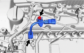
Disconnect the pressure discharge valve connector from the common rail assembly.
Remove the bolt and wiring harness clamp bracket from the cylinder head cover sub-assembly.
10.REMOVE HARNESS BRACKET
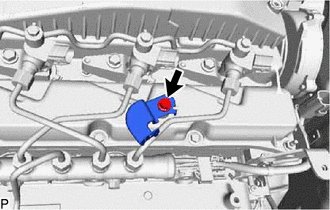
Remove the bolt and harness bracket.
23760
11.REMOVE NOZZLE LEAKAGE PIPE ASSEMBLY
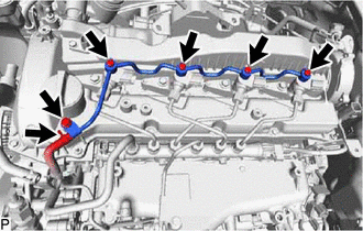
Slide the clamp and disconnect the No. 5 fuel hose from the nozzle leakage pipe assembly.
Remove the 4 union bolts and 4 gaskets.
Remove the bolt and nozzle leakage pipe assembly.
12.REMOVE NO. 1 AND NO. 2 INJECTION PIPE SUB-ASSEMBLY
- NOTICE:
-
After removing the No. 1 and No. 2 injection pipe sub-assemblies, cover the common rail assembly with electrical tape to prevent dirt or foreign objects from entering the pipe inlet. Also, protect the injector inlets with electrical tape or plastic bags.
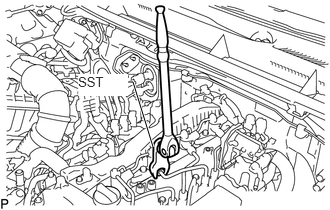
Using SST, loosen the No. 1 and No. 2 injection pipe sub-assemblies and 8 union nuts of the fuel injector assembly side and common rail assembly side.
- SST
- 09245-11010
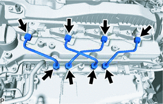
Remove the 2 No. 1 injection pipe sub-assemblies and 2 No. 2 injection pipe sub-assemblies.
- NOTICE:
-
When removing the No. 1 injection pipe sub-assembly and No. 2 injection pipe sub-assembly, store the injector assemblies in the correct order so that they can be returned to their original locations when reassembling.
23670
13.REMOVE INJECTOR ASSEMBLY
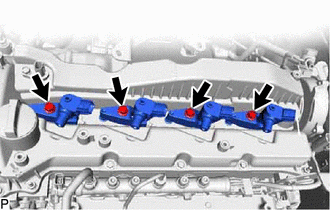
Remove the 4 nozzle holder clamp bolts, 4 washers and 4 nozzle holder clamps.
Remove the 4 fuel injector assemblies and 4 injection nozzle seats from the cylinder head sub-assembly.
- NOTICE:
-
When removing the injector assembly, store the injector assemblies in the correct order so that they can be returned to their original locations when reassembling.
Remove the O-ring from each injector assembly.
23682
14.REMOVE NOZZLE HOLDER GASKET
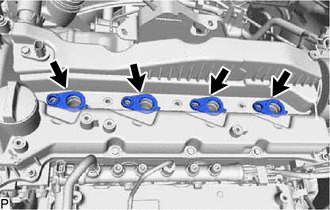
Remove the 4 nozzle holder gaskets from the cylinder head cover sub-assembly.