FRONT SUSPENSION FRONT SUSPENSION MEMBER REMOVAL
CAUTION / NOTICE / HINT
The necessary procedures (adjustment, calibration, initialization, or registration) that must be performed after parts are removed and installed, or replaced during front frame assembly removal/installation are shown below.
| Replacement Part or Procedure | Necessary Procedure | Effect/Inoperative when not Performed | Link |
|---|---|---|---|
| Disconnect cable from negative battery terminal | Memorize steering angle neutral point | Parking assist monitor system | ( ) |
| Panoramic view monitor system | ()
|
||
| ECM | for 7GR-FKS:
Perform Vehicle Identification Number (VIN) or frame number registration |
DTC P063051 is output | ()
|
for 1GD-FTV:
Perform Vehicle Identification Number (VIN) or frame number registration |
DTC is stored | w/ DPF:()
w/ EGR Cooler:( )
for Water Cooled Type Intercooler:( )
w/o EGR Cooler:( )
|
|
| ECU communication ID registration | Engine start function | See Service Bulletin for the registration method. | |
for RC60J:
Performing iMT installation information reset |
·
iMT system ·
DTCs are output |
for 7GR-FKS:()
for 1GD-FTV:( )
|
|
for 7GR-FKS:
·
Engine assembly ·
Air leaks from intake system ·
Gas leaks from exhaust system |
Inspection after repair | ·
Poor idle, etc. ·
Engine start function, etc. |
()
|
for 1GD-FTV:
Engine assembly |
Clear crank time compensation data | Engine starting | w/ DPF:()
w/ EGR Cooler:( )
for Water Cooled Type Intercooler:( )
w/o EGR Cooler:( )
|
·
Input injector compensation code ·
Pilot quantity learning |
Engine starting | w/ DPF:()
w/ EGR Cooler:( )
for Water Cooled Type Intercooler:( )
w/o EGR Cooler:( )
|
|
w/ Stop and Start System:
Starter assembly
|
Clear the number of starter operations | Stop and start system | ()
|
for AE60E:
·
Automatic transmission assembly ·
Transmission valve body assembly ·
Any of the shift solenoid valve |
Reset memory | ·
Large shift shock ·
Engine overruns |
7GR-FKS:()
1GD-FTV:( )
|
for AE60E:
Automatic transmission fluid |
ATF thermal degradation estimate reset | The value of the Data List item "ATF Thermal Degradation Estimate" is not estimated correctly | |
| Front wheel alignment adjustment | ·
Perform reset memory ·
Perform acceleration sensor zero point calibration and store system information memorization. |
·
VSC is disabled or malfunctions ·
DTCs are output ·
Slip indicator light illuminates ·
ABS warning light illuminates |
()
|
| Suspension, tires, etc. | Television camera assembly optical axis (Back camera position setting) | Parking assist monitor system | ()
|
·
Parking assist ECU initialization ·
Adjust steering angle |
Panoramic view monitor system | ()
|
|
| Replacement of the rear height control sensor sub-assembly LH, removal and reinstallation of the rear height control sensor sub-assembly LH, replacement of the suspension, etc. have been performed | Perform headlight ECU sub-assembly LH initialization | Lighting system (EXT) | ()
|
- CAUTION:
- ·
 2.219,0.813 2.646,0.813 false 2.698,0.729 3.01,0.927 0.313,0.198 10 false *a
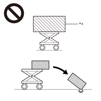
*a An Object Exceeding Weight Limit of Engine Lifter
The engine assembly with transaxle is very heavy. Be sure to follow the procedure described in the repair manual, or the engine lifter may suddenly drop or the engine assembly with transaxle may fall off the engine lifter.
·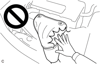
To prevent burns, do not touch the engine, exhaust manifold or other high temperature components while the engine is hot.
- HINT:
-
When the cable is disconnected / reconnected to the battery terminal, systems temporarily stop operating. However, each system has a function that completes learning the first time the systems is used.
- ·
Learning completes when vehicle is driven
Effect/Inoperative Function When Necessary Procedures are not Performed Necessary Procedures Link *: w/ Stop and start system
Stop and start system* Drive the vehicle until stop and start control is permitted (approximately 5 to 60 minutes). ( )
Lane control system Drive the vehicle straight ahead at 15 km/h (10 mph) or more for 1 second or more. ( )
Pre-collision system
·Learning completes when vehicle is operated normally
Effect/Inoperative Function When Necessary Procedures are not Performed Necessary Procedures Link Power slide door system Fully close the slide door by hand.
- HINT:
-
Initialization is not necessary if the above procedures are performed while the slide door is closed.
( )
Air conditioning system After the ignition switch is turned to ON, the servo motor standard position is recognized. -
PROCEDURE

 1. PRECAUTION
- NOTICE:
-
After turning the ignition switch off, waiting time may be required before disconnecting the cable from the negative (-) battery terminal.
-
Click hereGeneral>SETUP>WHEN DISCONNECTING OR RECONNECTING BATTERY TERMINAL>BEFORE DISCONNECTING BATTERY
51100H
2.DISCONNECT FRONT FRAME ASSEMBLY
for 7GR-FKS:
Click hereEngine / Hybrid System>7GR-FKS (ENGINE MECHANICAL)>ENGINE ASSEMBLY>REMOVAL
for 1GD-FTV:
Click hereEngine / Hybrid System>1GD-FTV (ENGINE MECHANICAL)>ENGINE ASSEMBLY>REMOVAL
3.REMOVE FRONT STABILIZER BAR WITH BRACKET
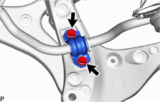
Remove the 2 bolts and separate the front No. 1 stabilizer bracket LH from the front frame assembly.
Remove the 2 bolts and separate the front No. 1 stabilizer bracket RH from the front frame assembly.
Remove the front stabilizer bar with the front No. 1 stabilizer bracket LH, front No. 1 stabilizer bracket RH, front No. 1 stabilizer bar bushing LH and front No. 1 stabilizer bar bushing RH from the front frame assembly.
44250
4.REMOVE RACK AND PINION POWER STEERING GEAR ASSEMBLY
for LHD:
Click hereSteering>STEERING GEAR / LINKAGE>STEERING GEAR (for LHD)>REMOVAL
for RHD:
Click hereSteering>STEERING GEAR / LINKAGE>STEERING GEAR (for RHD)>REMOVAL
48069
5.REMOVE FRONT LOWER NO. 1 SUSPENSION ARM SUB-ASSEMBLY LH
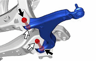
Remove the 2 bolts, 2 nuts and front lower No. 1 suspension arm sub-assembly LH from the front frame assembly.
48068
6.REMOVE FRONT LOWER NO. 1 SUSPENSION ARM SUB-ASSEMBLY RH
- HINT:
-
Perform the same procedure as for the LH side.
7.REMOVE HOLE PLUG
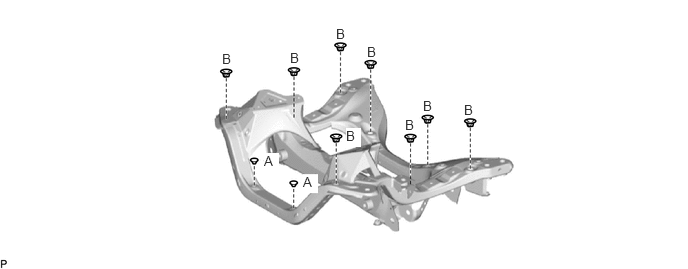
Remove the 10 hole plugs from the front frame assembly.
- HINT:
-
There are 2 different shapes of hole plug.