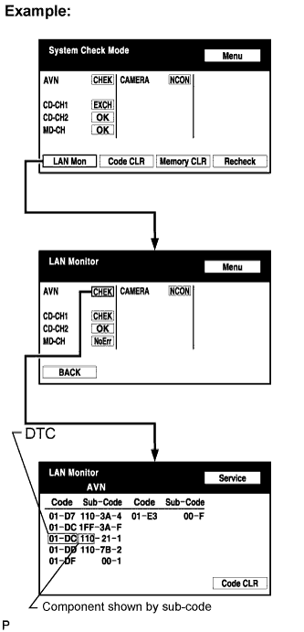
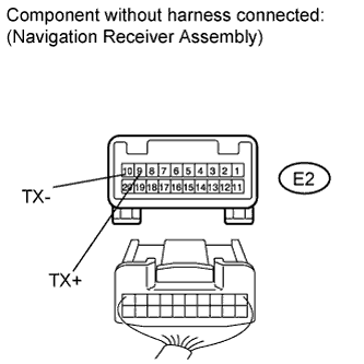
4. CHECK HARNESS AND CONNECTOR (NAVIGATION RECEIVER - COMPONENT SHOWN BY SUB-CODE)
HINT:
Start the check from the circuit that is near the component shown by the sub-code first.
For details of the connectors, refer to "TERMINALS OF ECU" (Click here).
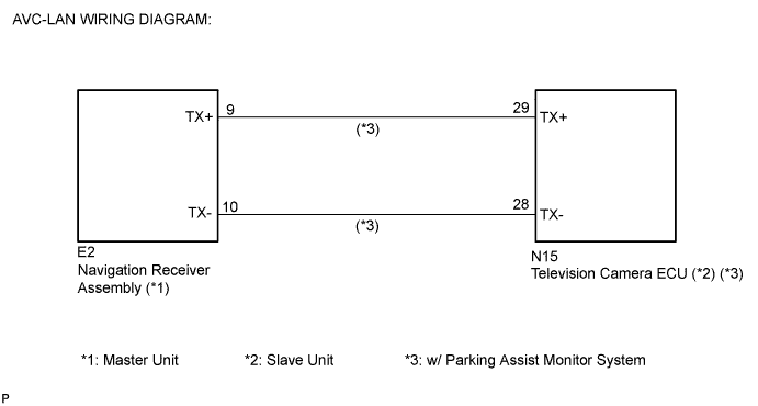
Referring to the AVC-LAN wiring diagram below, check the AVC-LAN circuit between the navigation receiver assembly and the component shown by the sub-code.
Disconnect all connectors between the navigation receiver assembly and the component shown by the sub-code.
Check for an open or short in the AVC-LAN circuit between the navigation receiver assembly and the component shown by the sub-code.
OK:
There are no open or short circuits.
NG
REPAIR OR REPLACE HARNESS OR CONNECTOR
OK
5. REPLACE COMPONENT SHOWN BY SUB-CODE
Replace the component shown by the sub-code with a normal one and check if the same problem occurs again.