| B |  |
| GO TO DTC CHART (P0A1F-129) (Click here) |
| C | |
| REPLACE INVERTER WITH CONVERTER ASSEMBLY (Click here) |
| D | |
| GO TO DTC CHART (P0A94-585) (Click here) |
DTC P0A94-587 DC / DC Converter Performance |
| DTC No. | INF Code | DTC Detection Condition | Trouble Area |
| P0A94 | 587 | Voltages from HV battery voltage (VB) sensor and boost converter voltage (VL) sensor deviate |
|
| Related DTCs | P0A94 (INF 587): Voltage (VB or VL) sensor |
| Required sensors / components | Boost converter |
| Frequency of operation | Continuous |
| Duration | TMC's intellectual property |
| MIL operation | Immediately |
| Sequence of operation | None |
| The monitor will run whenever the DTCs listed are not present | TMC's intellectual property |
| Other conditions belong to TMC's intellectual property | - |
| TMC's intellectual property | - |
| Boost converter | DTC P0A94 (INF 587) is not detected |
| 1.CHECK DTC OUTPUT (HV) |
Connect the Techstream to the DLC3.
Turn the power switch on (READY).
Select the following menu items: Powertrain / Hybrid Control / Trouble Codes.
Check if DTCs are output.
| Output DTC | Proceed to |
| DTC P0A94-587 only, or DTCs other than below | A |
| DTCs P0A94-587 and P0A1F-129 (HV battery voltage circuit malfunction) | B |
| DTCs P0A94-587 and P0A94-442 (Abnormal voltage execution value) | C |
| DTCs P0A94-587 and P0A94-585 (Boost converter voltage (VL) sensor performance problem) | D |
|
| ||||
|
| ||||
|
| ||||
| A | |
 |
| 2.CHECK DTC OUTPUT (HV) |
Connect the Techstream to the DLC3.
Turn the power switch on (READY).
Move the shift lever to the N position.
Turn the A/C switch to the MAX COOL position.
Select the following menu items: Powertrain / Hybrid Control / Data List / Power Resource IB.
Confirm that the "Power Resource IB" is more than 3 A.
Leave the vehicle in the above condition for 15 seconds.
Select the following menu items: Powertrain / Hybrid Control / Trouble Codes.
Check if DTCs are output.
| DTC No. | Relevant Diagnosis | Proceed to |
| No DTC is output. | - | A |
| P0A1F-129 | HV battery voltage circuit malfunction | B |
| P0A94-585 | Boost converter voltage (VL) sensor performance problem | C |
| P3000-388 | Discharge inhibition | D |
| P3004-132 | High voltage power supply line problem | E |
|
| ||||
|
| ||||
|
| ||||
|
| ||||
| A | |
|
| 3.CHECK DTC OUTPUT (HV) |
Connect the Techstream to the DLC3.
Select the following menu items: Powertrain / Hybrid Control / Data List / Power Resource VB, VL-Voltage before Boosting and VH-Voltage after Boosting.
Test-drive the vehicle while monitoring the HV battery, pre-boost, and post-boost voltages in the ECU data list.
Check for DTCs and check the result of monitoring the data list.
| DTC No. | Relevant Diagnosis | Proceed to |
| P0A1F-129 | HV battery voltage circuit malfunction | B |
| P0A94-585 | Boost converter voltage (VL) sensor performance problem | C |
| P3000-388 | Discharge inhibition | D |
| P3004-132 | High voltage power supply line problem | E |
| ECU Data List | Result | Proceed to |
| VB | Deviates from the data behavior shown below | B |
| VL | Deviates from the data behavior shown below | C |
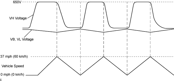
|
| ||||
|
| ||||
|
| ||||
|
| ||||
| A | |
|
| 4.REPLACE BATTERY SMART UNIT |
Replace the battery smart unit (Click here).
| NEXT | ||
 | ||
| ||