2GR-FE COOLING WATER PUMP INSTALLATION
PROCEDURE

 16100
1.INSTALL ENGINE WATER PUMP ASSEMBLY
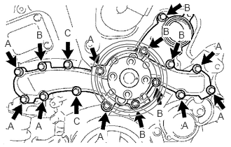
Install a new water pump gasket and engine water pump assembly together with the water pump pulley with the 16 bolts.
- Torque:
- Bolt (A) : 21 N*m (214 kgf*cm, 15 ft.*lbf)
- Bolt (B) and (C) : 11 N*m (112 kgf*cm, 8 ft.*lbf)
- NOTICE:
- ·
Make sure that there is no oil on the threads of the bolts (A).
·Be sure to replace the 2 bolts (C) with new ones or reuse them after applying adhesive.
·Do not start the engine within 1 hour of installation.
- Adhesive:
Toyota Genuine Adhesive 1344, Three Bond 1344 or equivalent
16173
2.INSTALL WATER PUMP PULLEY
Temporarily install the water pump pulley with the 4 bolts.
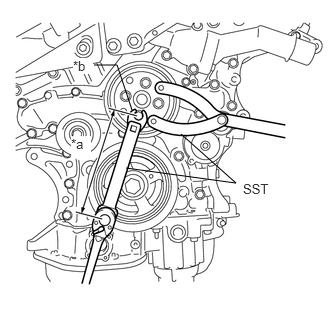
| *a | Length of SST and Union Nut Wrench 170 mm (6.69 in.) |
| *b | 12 mm Union Nut Wrench |
Using SST, hold the water pump pulley.
- SST
- 09960-10010 (09962-01000, 09963-00700)
Using SST and 12 mm union nut wrench, tighten the 4 bolts.
- SST
- 09961-00950
- Torque:
- without SST [Torque (N*m (kgf*cm, ft.*lbf))] : 21 N*m (214 kgf*cm, 15 ft.*lbf)
- with SST [Reading of Torque wrench (N*m (kgf*cm, ft.*lbf))] : 11 N*m (112 kgf*cm, 8 ft.*lbf)
- HINT:
- ·
This torque value is effective when SST is parallel to the torque wrench.
·The "with SST" torque value is effective when using SST and union nut wrench with a fulcrum length of 170 mm (6.69in.).
·The "with SST" torque value is effective when using a torque wrench with a fulcrum length of 180 mm (7.09 in.).
·If using a torque wrench with a different length, or connecting the torque wrench, SST and union nut wrench at an angle, refer to the alternate torque values.
Click hereGeneral>INTRODUCTION>REPAIR INSTRUCTION>PRECAUTION
16323
3.INSTALL WATER INLET HOUSING
Install 2 new O-rings.
Install the water inlet housing with the 2 bolts and nut.
- Torque:
- 10 N*m (102 kgf*cm, 7 ft.*lbf)
- NOTICE:
-
Be careful not to allow the O-ring to get caught between the parts.
Connect the water by-pass hose and slide the clip to secure it.
4.INSTALL V-RIBBED BELT TENSIONER PULLEY
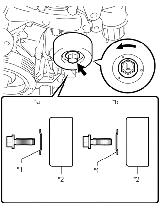
| *1 | Dust Shield |
| *2 | V-ribbed Belt Tensioner Pulley |
| *a | Correct |
| *b | Incorrect |
Install the V-ribbed belt tensioner pulley and dust shield with the bolt.
- NOTICE:
- ·
Be careful when tightening the bolt because its thread is left-handed.
·Install the dust shield in the direction shown in the illustration. Failure to do so may cause looseness.
·Make sure to use the removed bolt. (Do not use another bolt even if it is the same size.)
- Torque:
- 48 N*m (489 kgf*cm, 35 ft.*lbf)
Install a 5 mm bi-hexagon wrench.
16604
5.INSTALL NO. 2 IDLER PULLEY SUB-ASSEMBLY
12315
6.INSTALL FRONT NO. 1 ENGINE MOUNTING BRACKET LH
Temporarily install the front No. 1 engine mounting bracket LH with the 6 bolts.
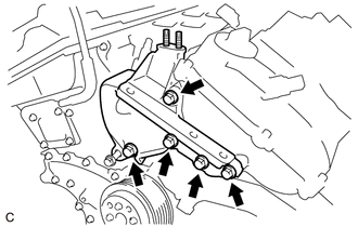
Fully tighten the 5 bolts.
- Torque:
- 54 N*m (551 kgf*cm, 40 ft.*lbf)
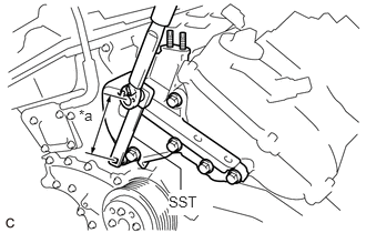
| *a | Length of SST 150 mm (5.91 in.) |
Using SST, fully tighten the bolt.
- SST
- 09961-00950
- Torque:
- without SST [Torque (N*m (kgf*cm, ft.*lbf))] : 54 N*m (551 kgf*cm, 40 ft.*lbf)
- with SST [Reading of Torque wrench (N*m (kgf*cm, ft.*lbf))] : 34 N*m (347 kgf*cm, 25 ft.*lbf)
- HINT:
- ·
This torque value is effective when SST is parallel to the torque wrench.
·The "with SST" torque value is effective when using SST with a fulcrum length of 150 mm (5.91 in.).
·The "with SST" torque value is effective when using a torque wrench with a fulcrum length of 260 mm (10.2 in.).
·If using a torque wrench with a different length, or connecting the torque wrench and SST at an angle, refer to the alternate torque values.
Click hereGeneral>INTRODUCTION>REPAIR INSTRUCTION>PRECAUTION
Lower the engine, and remove the jack.
12362
7.INSTALL ENGINE MOUNTING INSULATOR RH
Install the engine mounting insulator RH with the 3 nuts.
- Torque:
- 99 N*m (1010 kgf*cm, 73 ft.*lbf)
Install the 2 hole plugs.
12360
8.INSTALL FRONT ENGINE MOUNTING INSULATOR ASSEMBLY
Install the front engine mounting insulator assembly with the 3 nuts.
- Torque:
- 58 N*m (591 kgf*cm, 43 ft.*lbf)
Install the hole plug.
12380
9.INSTALL REAR ENGINE MOUNTING INSULATOR ASSEMBLY
Install the rear engine mounting insulator assembly with the 2 nuts.
- Torque:
- 58 N*m (591 kgf*cm, 43 ft.*lbf)
Install the 2 hole plugs.
11322F
10.INSTALL NO. 2 TIMING GEAR COVER
12313
11.INSTALL ENGINE MOVING CONTROL ROD BRACKET
12327A
12.INSTALL NO. 2 ENGINE MOUNTING STAY RH (for Intake Manifold Side)
12327A
13.INSTALL NO. 2 ENGINE MOUNTING STAY RH (for Engine Mounting Stay Side)
16572D
14.CONNECT NO. 2 RADIATOR HOSE
16361A
15.INSTALL V-RIBBED BELT
16.ADD ENGINE COOLANT
17.INSPECT FOR COOLANT LEAK
11209
18.INSTALL V-BANK COVER SUB-ASSEMBLY