2GR-FE COOLING WATER PUMP REMOVAL
PROCEDURE

 11209
1.REMOVE V-BANK COVER SUB-ASSEMBLY
2.DRAIN ENGINE COOLANT
16361A
3.REMOVE V-RIBBED BELT
16572D
4.DISCONNECT NO. 2 RADIATOR HOSE
12327A
5.REMOVE NO. 2 ENGINE MOUNTING STAY RH (for Engine Mounting Stay Side)
12327A
6.REMOVE NO. 2 ENGINE MOUNTING STAY RH (for Intake Manifold Side)
12313
7.REMOVE ENGINE MOVING CONTROL ROD BRACKET
11322F
8.REMOVE NO. 2 TIMING GEAR COVER
12380
9.SEPARATE REAR ENGINE MOUNTING INSULATOR ASSEMBLY
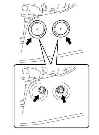
Remove the 2 hole plugs.
Remove the 2 nuts and separate the rear engine mounting insulator assembly.
12360
10.SEPARATE FRONT ENGINE MOUNTING INSULATOR ASSEMBLY
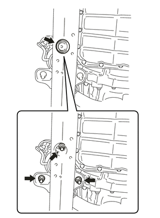
Remove the hole plug.
Remove the 3 nuts and separate the front engine mounting insulator assembly.
12362
11.SEPARATE ENGINE MOUNTING INSULATOR RH
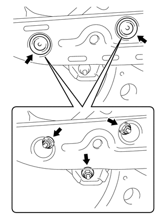
Remove the 2 hole plugs.
Remove the 3 nuts and separate the engine mounting insulator RH.
12315
12.REMOVE FRONT NO. 1 ENGINE MOUNTING BRACKET LH
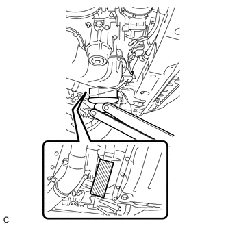

|
Wooden Block Placement Location |
Place a wooden block between a jack and the engine.
- NOTICE:
-
Make sure to set a jack as shown in the illustration. Do not place the jack under the oil pan.
Jack up the engine slightly.
- NOTICE:
-
Do not jack up the engine excessively.
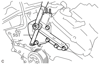
Using SST, remove the bolt.
- SST
- 09961-00950
- HINT:
-
There is not enough clearance to completely remove the bolt from the front No. 1 engine mounting bracket LH. Remove the front No. 1 engine mounting bracket LH together with the bolt.
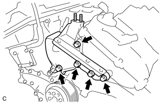
Remove the 5 bolts.
Remove the front No. 1 engine mounting bracket LH together with the bolt.
16604
13.REMOVE NO. 2 IDLER PULLEY SUB-ASSEMBLY
14.REMOVE V-RIBBED BELT TENSIONER PULLEY
Remove the 5 mm bi-hexagon wrench.
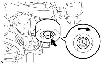
Remove the bolt, dust shield and V-ribbed belt tensioner pulley.
- NOTICE:
- ·
Do not turn the bolt labeled "L" counterclockwise.
·Store the V-ribbed belt tensioner pulley so that the bearing does not get damaged.
16323
15.REMOVE WATER INLET HOUSING
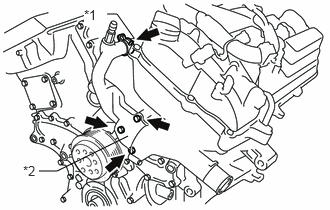
| *1 | Water By-pass Hose |
| *2 | Water Inlet Housing |
Slide the clip and disconnect the water by-pass hose.
Remove the 2 bolts, nut and water inlet housing.
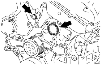
Remove the 2 O-rings.
16173
16.REMOVE WATER PUMP PULLEY
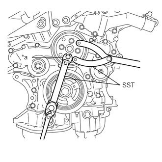
| *a | 12 mm Union Nut Wrench |
Using SST, hold the water pump pulley.
- SST
- 09960-10010 (09962-01000, 09963-00700)
Using SST and a 12 mm union nut wrench, remove the 4 bolts and separate the water pump pulley from the engine water pump assembly.
- SST
- 09961-00950
- HINT:
-
There is not enough clearance to completely remove the water pump pulley from the water pump shaft. Remove the water pump pulley together with the engine water pump assembly.
16100
17.REMOVE ENGINE WATER PUMP ASSEMBLY
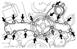
Remove the 16 bolts, engine water pump assembly, water pump pulley and water pump gasket.