BRAKE SYSTEM (OTHER) VACUUM PUMP INSTALLATION
PROCEDURE

 29300
1.INSTALL VACUUM PUMP ASSEMBLY
Clean the vacuum pump assembly installation bolt holes in the camshaft housing sub-assembly and cylinder head sub-assembly.
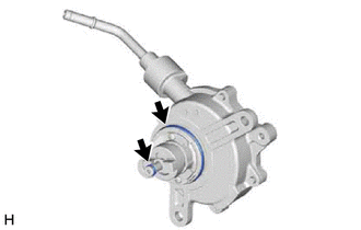
When using a new vacuum pump assembly:

|
Engine oil |
Apply engine oil to the 2 O-rings which are installed to a new vacuum pump assembly.
When reusing the vacuum pump assembly:
|
|
Engine oil |
Apply engine oil to 2 new O-rings and install them to the vacuum pump assembly.
Apply engine oil to the inner surface of the installation hole.
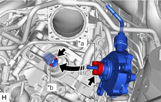
| *a | Coupling Teeth |
| *b | Groove |
Install the vacuum pump assembly so that the oil pipe engages with the hole of the camshaft and the coupling teeth with the grooves on the camshaft tip.
- NOTICE:
- ·
Ensure that the vacuum pump assembly is installed securely.
·Be careful not to pinch the O-ring.
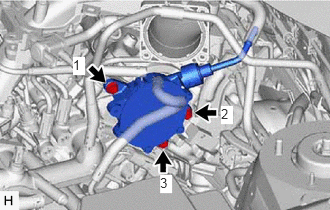
Install the vacuum pump assembly with 3 new bolts.
- Torque:
- 21 N*m (214 kgf*cm, 15 ft.*lbf)
- NOTICE:
- ·
After installation, check that there are no gaps between the matching surfaces and that the vacuum pump assembly is not installed at an angle.
·Tighten the 3 bolts in the order shown in the illustration.
82121
2.INSTALL ENGINE WIRE
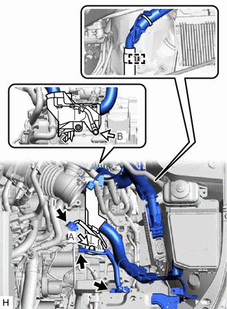
|
|
Connector |

|
Bolt |

|
Nut |
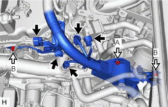
Install the engine wire with the bolt (A) and nut.
Install the bolt (B).
- Torque:
- 19.1 N*m (195 kgf*cm, 14 ft.*lbf)
Connect the 3 connectors.
Engage the clamp.
|
|
Connector |
|
|
Bolt |
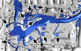
Install the bolt (A).
Install the 2 bolts (B).
- Torque:
- 8.5 N*m (87 kgf*cm, 75 in.*lbf)
Connect the 5 connectors.
|
|
Connector |
|
|
Bolt |
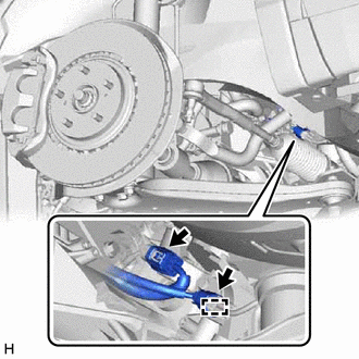
Install the 2 bolts.
Engage the claw.
Connect the 11 connectors.
Engage the clamp.
Connect the 2 connectors.
51442
3.INSTALL NO. 2 ENGINE UNDER COVER
4.CONNECT HEATER WATER HOSE
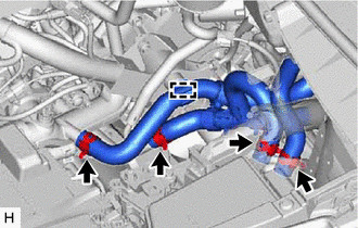
Connect the 4 heater water hoses, and slide the 4 clips to secure them.
Engage the clamp.
12261
5.CONNECT VENTILATION HOSE
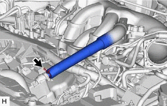
Connect the ventilation hose, and slide the clip to secure it.
17361M
6.CONNECT AIR TUBE
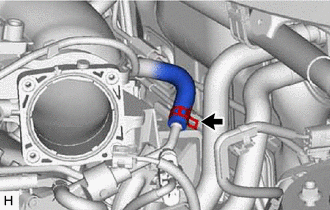
Connect the air tube to the vacuum pump assembly, and slide the clip to secure it.
33820B
7.INSTALL TRANSMISSION CONTROL CABLE ASSEMBLY
Install a new clip to the No. 1 transmission control cable bracket.
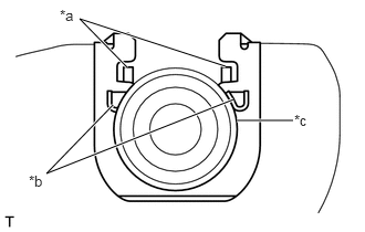
| *a | Claw A |
| *b | Claw B |
| *c | Transmission Control Cable Assembly |
Connect the transmission control cable assembly to the No. 1 transmission control cable bracket.
- NOTICE:
- ·
Make sure that the claws A on the clip are securely fit into the No. 1 transmission control cable bracket holes.
·Make sure that the transmission control cable assembly is securely installed inside of the claws B of the clip.
Connect the transmission control cable assembly to the transmission control shaft lever and install the clip.
- NOTICE:
-
Before connecting the transmission control cable assembly, check that the park/neutral position switch assembly and the shift lever are in neutral.
17701
8.INSTALL AIR CLEANER CASE SUB-ASSEMBLY
17801
9.INSTALL AIR CLEANER FILTER ELEMENT SUB-ASSEMBLY
17750A
10.INSTALL INLET AIR CLEANER ASSEMBLY
11209
11.INSTALL V-BANK COVER SUB-ASSEMBLY
53295E
12.INSTALL COOL AIR INTAKE DUCT SEAL
53298E
13.INSTALL RADIATOR SIDE SEAL RH
53299D
14.INSTALL RADIATOR SIDE DEFLECTOR SEAL LH
15.INSTALL FRONT WHEEL LH
- Torque:
- 103 N*m (1050 kgf*cm, 76 ft.*lbf)
16.CONNECT CABLE TO NEGATIVE BATTERY TERMINAL
- NOTICE:
-
When disconnecting the cable, some systems need to be initialized after the cable is reconnected.
-
Click hereGeneral>INTRODUCTION>REPAIR INSTRUCTION>INITIALIZATION
22030
17.INSTALL THROTTLE BODY WITH MOTOR ASSEMBLY
18.INSPECT VACUUM PUMP OPERATION
55701J
19.INSTALL OUTER COWL TOP PANEL SUB-ASSEMBLY
for LHD: Click hereSuspension>FRONT SUSPENSION>FRONT SHOCK ABSORBER>INSTALLATION
for RHD: Click hereSuspension>FRONT SUSPENSION>FRONT SHOCK ABSORBER>INSTALLATION
20.INSTALL WINDSHIELD WIPER MOTOR AND LINK ASSEMBLY