BRAKE SYSTEM (OTHER) BRAKE BOOSTER(for LHD) INSTALLATION
PROCEDURE

 44785
1.INSTALL BRAKE BOOSTER GASKET
Install a new brake booster gasket to the brake booster assembly.
44610
2.INSTALL BRAKE BOOSTER ASSEMBLY
Temporarily install the brake booster assembly to the vehicle body.
- NOTICE:
-
Do not apply excessive force to the brake lines or refrigerant lines.
Temporarily install the lock nut and brake master cylinder push rod clevis to the brake booster assembly.
- NOTICE:
-
Fully tighten the lock nut when adjusting the brake pedal height.
Install the 4 nuts to secure the brake booster assembly.
- Torque:
- 12.7 N*m (130 kgf*cm, 9 ft.*lbf)
47264A
3.INSTALL PUSH ROD PIN
47101A
4.INSTALL BRAKE PEDAL RETURN SPRING
5.INSTALL BRAKE LINE
Install the 3 brake lines to the brake tube clamp.
- NOTICE:
- ·
Do not kink or damage the brake lines.
·Do not damage the clamp.
Install the bolt to secure front No. 1 brake tube way.
- Torque:
- 4.9 N*m (50 kgf*cm, 43 in.*lbf)
- NOTICE:
-
Do not kink or damage the brake lines.
6.INSTALL AIR CONDITIONER TUBE AND ACCESSORY ASSEMBLY
Install the air conditioner tube and accessory assembly with the nut.
- Torque:
- 9.8 N*m (100 kgf*cm, 87 in.*lbf)
- NOTICE:
- ·
Do not deform the refrigerant lines.
·Do not damage the clamp.
88704
7.INSTALL SUCTION HOSE SUB-ASSEMBLY
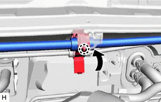
Install the suction hose sub-assembly to the piping clamp.
- NOTICE:
- ·
Do not deform the refrigerant lines.
·Do not damage the clamp.
Engage the claw to secure the suction hose sub-assembly.
44777
8.CONNECT NO. 1 VACUUM HOSE CONNECTOR (for 1AR-FE)
Install the No. 1 vacuum hose connector with the 2 nuts.
- Torque:
- 5.4 N*m (55 kgf*cm, 48 in.*lbf)
Connect the union to check valve hose to the brake booster assembly, and slide the clip to secure it.
23820
9.CONNECT FUEL VAPOR FEED HOSE ASSEMBLY
Connect the fuel vapor feed hose assembly, and slide the clip to secure it.
82111
10.INSTALL ENGINE ROOM MAIN WIRE
Engage the 2 pins to install the engine room relay block assembly.
Install the 2 bolts.
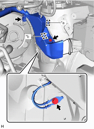
| *a | Clamp |
| *b | Pin |
Engage the clamp and pin to install the wire harness protector.
Install the bolt to secure the wire harness protector.
Install the earth wire with the bolt.
- Torque:
- 8.5 N*m (87 kgf*cm, 75 in.*lbf)
for 2GR-FKS:
Connect the connector to the vacuum warning switch assembly.
Engage the 5 clamps to install the engine room main wire.
82121
11.INSTALL ENGINE WIRE (for 1AR-FE)
Engage the 3 clamps to install the engine wire.
82121
12.INSTALL ENGINE WIRE (for 2GR-FKS)
Engage the 2 clamps to install the engine wire.
44773F
13.CONNECT UNION TO CHECK VALVE HOSE (for 2GR-FKS)
Connect the union to check valve hose to the brake booster assembly, and slide the clip to secure it.
Install the union to check valve hose to the engine room main wire.
89661
14.INSTALL ECM
for 1AR-FE: Click hereEngine / Hybrid System>1AR-FE ENGINE CONTROL>ECM>INSTALLATION
for 2GR-FKS: Click hereEngine / Hybrid System>2GR-FKS (ENGINE CONTROL)>ECM>INSTALLATION
47233
15.INSTALL RESERVOIR BRACKET
Install the reservoir bracket with the 2 bolts.
- Torque:
- 9.0 N*m (92 kgf*cm, 80 in.*lbf)
47220D
16.INSTALL BRAKE MASTER CYLINDER RESERVOIR ASSEMBLY
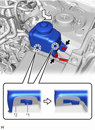
| *1 | Brake Master Cylinder Reservoir Assembly |
| *2 | Reservoir Bracket |
Move the brake master cylinder reservoir assembly as shown in the illustration to engage the 2 claws.
Connect the reservoir level switch connector and install the bolt.
- Torque:
- 9.0 N*m (92 kgf*cm, 80 in.*lbf)
55701J
17.INSTALL OUTER COWL TOP PANEL SUB-ASSEMBLY
18.INSTALL WINDSHIELD WIPER MOTOR AND LINK ASSEMBLY
19.INSTALL BRAKE MASTER CYLINDER SUB-ASSEMBLY WITH WAY
20.INSPECT AND ADJUST BRAKE PEDAL