REAR SUSPENSION REAR LOWER ARM INSTALLATION
CAUTION / NOTICE / HINT
- HINT:
- ·
Use the same procedure for the RH side and LH side.
·The following procedure is for the LH side.
PROCEDURE

 48720A
1.TEMPORARILY INSTALL REAR NO. 1 SUSPENSION ARM ASSEMBLY
for Gasoline Model:
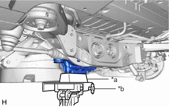
| *a | Wooden Block |
| *b | Transmission Jack |
Using a transmission jack and a wooden block, support the rear differential carrier assembly.
for HV Model:
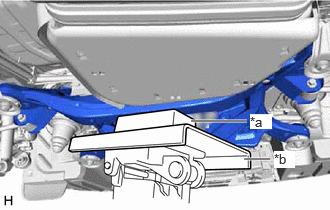
| *a | Wooden Block |
| *b | Transmission Jack |
Using a transmission jack and wooden block, support the rear suspension member sub-assembly.
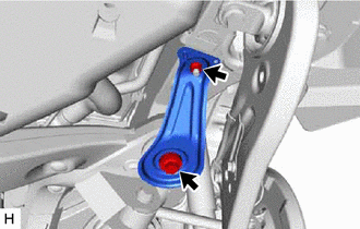
Remove the bolt, nut and rear lower suspension member stopper.
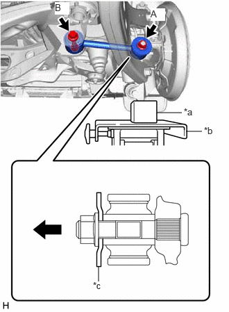
| *a | Wooden Block |
| *b | Jack |
| *c | Spacer |

|
Front of the Vehicle |
Using a transmission jack and a wooden block, support the rear axle carrier sub-assembly.
Temporarily install the rear No. 1 suspension arm assembly to the rear axle carrier sub-assembly with the spacer and nut (A).
- NOTICE:
-
Be sure to install the rear No. 1 suspension arm assembly with the spacer facing in the correct direction as shown in the illustration.
Temporarily install the rear No. 1 suspension arm assembly to the rear suspension member sub-assembly with the bolt (B) and nut.
- NOTICE:
- ·
Because the nut has its own stopper, do not turn the nut. Tighten the bolt with the nut secured.
·Insert the bolt with the threaded end facing the rear of the vehicle.
Install the rear lower suspension member stopper with the bolt and nut.
- Torque:
- Bolt : 158 N*m (1611 kgf*cm, 117 ft.*lbf)
- Nut : 32 N*m (326 kgf*cm, 24 ft.*lbf)
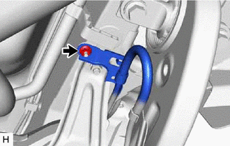
Install the No. 2 parking brake wire assembly to the rear lower suspension member stopper with the nut.
- Torque:
- 8.5 N*m (87 kgf*cm, 75 in.*lbf)
48740F
2.TEMPORARILY INSTALL REAR NO. 2 SUSPENSION ARM ASSEMBLY
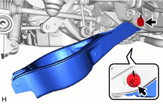
Temporarily install the rear No. 2 suspension arm assembly to the rear suspension member sub-assembly with the rear No. 2 suspension camber adjust cam, rear suspension toe adjust cam sub-assembly and the nut.
- NOTICE:
- ·
Insert the rear suspension toe adjust cam sub-assembly from the rear of the vehicle.
·When tightening the nut, keep the rear suspension toe adjust cam sub-assembly from rotating.
48258C
3.INSTALL REAR LOWER COIL SPRING INSULATOR
48231B
4.INSTALL REAR COIL SPRING
5.CONNECT REAR STABILIZER LINK ASSEMBLY
6.STABILIZE SUSPENSION
48720A
7.INSTALL REAR NO. 1 SUSPENSION ARM ASSEMBLY
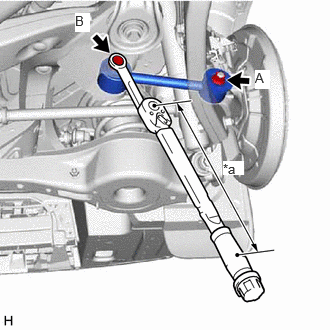
| *a | Torque Wrench Fulcrum Length |
Using a ball joint lock nut wrench, fully tighten the rear No. 1 suspension arm assembly with the bolt (B).
- Torque:
- Specified tightening torque : 125 N*m (1275 kgf*cm, 92 ft.*lbf)
- NOTICE:
-
Because the nut has its own stopper, do not turn the nut. Tighten the bolt with the nut secured.
- HINT:
- ·
Calculate the torque wrench reading when changing the fulcrum length of the torque wrench.
Click hereGeneral>INTRODUCTION>REPAIR INSTRUCTION>PRECAUTION
·When using a ball joint lock nut wrench (fulcrum length of 150 mm (5.91 in.)) + torque wrench (fulcrum length of 400 mm (1.31 ft.)):
91 N*m (928 kgf*cm, 67 ft.*lbf)
Fully tighten the rear No. 1 suspension arm assembly with the nut (A).
- Torque:
- 135 N*m (1377 kgf*cm, 100 ft.*lbf)
48740F
8.INSTALL REAR NO. 2 SUSPENSION ARM ASSEMBLY
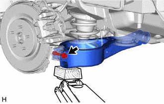
Install the rear No. 2 suspension arm assembly (rear axle carrier sub-assembly side) with the bolt.
- Torque:
- 100 N*m (1020 kgf*cm, 74 ft.*lbf)
- NOTICE:
-
Because the nut has its own stopper, do not turn the nut. Tighten the bolt with the nut secured.
48738
9.INSTALL REAR SUSPENSION ARM COVER
Engage the 2 guides to install the rear suspension arm cover.
Install the rear suspension arm cover to the rear No. 2 suspension arm assembly with the 2 bolts.
- Torque:
- 12 N*m (122 kgf*cm, 9 ft.*lbf)
17430
10.INSTALL TAIL EXHAUST PIPE ASSEMBLY (for RH Side)
A25A-FXS, A25B-FXS: Click hereEngine / Hybrid System>A25A-FXS, A25B-FXS (INTAKE / EXHAUST)>EXHAUST PIPE>INSTALLATION
for 2GR-FKS: Click hereEngine / Hybrid System>2GR-FKS (INTAKE / EXHAUST)>EXHAUST PIPE>INSTALLATION
11.INSTALL REAR WHEEL
48740F
12.INSTALL REAR NO. 2 SUSPENSION ARM ASSEMBLY
Lower the vehicle to the ground.
Bounce the vehicle up and down at the corners to stabilize the rear suspension.
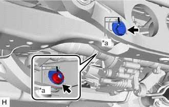
| *a | Matchmark |
Align the matchmarks on the rear No. 2 suspension camber adjust cam, rear suspension toe adjust cam sub-assembly and rear suspension member sub-assembly.
Fully tighten the nut.
- Torque:
- 100 N*m (1020 kgf*cm, 74 ft.*lbf)
- NOTICE:
- ·
Hold the rear suspension toe adjust cam sub-assembly while rotating the nut.
·Make sure that the vehicle is unloaded when fully tightening the nut.
13.INSPECT AND ADJUST REAR WHEEL ALIGNMENT
14.INSPECT FOR EXHAUST GAS LEAK (for RH Side)
A25A-FXS, A25B-FXS: Click hereEngine / Hybrid System>A25A-FXS, A25B-FXS (INTAKE / EXHAUST)>EXHAUST PIPE>INSTALLATION
for 2GR-FKS: Click hereEngine / Hybrid System>2GR-FKS (INTAKE / EXHAUST)>EXHAUST PIPE>INSTALLATION
15.PERFORM INITIALIZATION
| Parking Support Brake System | ( ) |
| Parking Assist Monitor System | ()
|
| Panoramic View Monitor System | ()
|