2GR-FKS ENGINE MECHANICAL ENGINE UNIT REMOVAL
CAUTION / NOTICE / HINT
The necessary procedures (adjustment, calibration, initialization or registration) that must be performed after parts are removed and installed, or replaced during engine unit removal/installation are shown below.
| Replaced Part or Performed Procedure | Necessary Procedure | Effect/Inoperative Function when Necessary Procedure not Performed | Link |
|---|---|---|---|
|
*1: Learning can also be performed using the GTS. Click here( *2: Not necessary when ECM replaced with new one *3: Even when not replacing the part, it is necessary to perform the specified necessary procedures after installation. *4: If the vehicle height has changed due to suspension or tire replacement |
|||
| Battery terminal is disconnected/reconnected | Perform steering sensor zero point calibration | Lane Control System | ( ) |
| Parking Support Brake System*1 | |||
| Pre-collision System | |||
| Memorize steering angle neutral point | Parking Assist Monitor System | ()
|
|
| Panoramic View Monitor System | ()
|
||
| Initialize back door lock | Power Door Lock Control System | ()
|
|
| Reset back door close position | Power Back Door System | ()
|
|
| Replacement of ECM | Perform Vehicle Identification Number (VIN) or frame number registration | DTC is output | ()
|
| Code registration | Engine start function | See Service Bulletin for the registration method | |
·
Replacement of throttle body with motor assembly ·
Cleaning the deposits from the throttle body with motor assembly ·
Replacement of engine assembly ·
Replacement of cylinder head sub-assembly ·
Replacement of camshaft (for intake or exhaust camshaft) ·
Replacement of camshaft timing gear assembly ·
Replacement of camshaft timing exhaust gear assembly ·
Replacement of fuel injector assembly (for port injection) ·
Replacement of fuel injector assembly (for direct injection) ·
Replacement of fuel pump assembly (for high pressure side) ·
Replacement of engine coolant temperature sensor ·
Replacement of spark plug ·
Replacement of ignition coil assembly ·
Air leaks from intake system ·
Gas leak from exhaust system is repaired ·
Replacement of knock control sensor |
Perform Inspection After Repair | ·
Poor idle, etc. ·
Engine start function, etc. |
()
|
| Replacement of automatic transaxle assembly | ·
Perform reset memory ·
Input transaxle compensation code into ECM ·
Perform road test to allow ECM to learn |
·
Large shift shock ·
Deterioration of fuel efficiency |
for Initialization:()
for Registration:( )
|
| Replacement of ECM
(If transaxle compensation code read from ECM) |
·
Perform reset memory*2 ·
Transfer transaxle compensation code ·
Perform road test to allow ECM to learn |
||
| Replacement of ECM
(If transaxle compensation code not read from ECM) |
·
Perform reset memory*2 ·
Reset transaxle compensation code ·
Perform road test to allow ECM to learn |
||
| Replacement of automatic transaxle fluid | ATF thermal degradation estimate reset | The value of the Data List item "ATF Thermal Degradation Estimate" is not estimated correctly | ()
|
| Replacement of front bumper assembly*3 | ·
Measurement of ultrasonic sensor detection angle ·
Ultrasonic sensor detection angle registration |
Parking Support Brake System | ()
|
| Front television camera view adjustment | Panoramic View Monitor System | ()
|
|
Replacement or removal and installation of 2 or more parts:
·
Front television camera assembly, radiator grille sub-assembly or front bumper assembly ·
Rear television camera assembly ·
Side television camera assembly LH or outer rear view mirror assembly LH ·
Side television camera assembly RH or outer rear view mirror assembly RH |
Television camera view adjustment | Panoramic View Monitor System | ()
|
| Suspension, tires, etc.*4 | ·
Measurement of ultrasonic sensor detection angle ·
Ultrasonic sensor detection angle registration |
Parking Support Brake System | ()
|
| Rear television camera assembly optical axis (Back camera position setting) | Parking Assist Monitor System | ()
|
|
·
Parking assist ECU initialization ·
Adjust steering angle |
Panoramic View Monitor System | ()
|
|
| Front wheel alignment adjustment | 1.
Perform "Reset Memory". 2.
Perform "Calibration". |
·
VSC is disabled or malfunctions ·
DTCs are output ·
Slip indicator light illuminates ·
ABS warning light illuminates |
()
|
PROCEDURE

 89615
1.REMOVE KNOCK CONTROL SENSOR
82219A
2.REMOVE SENSOR WIRE
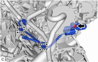
Disengage the 2 clamps and remove the bolt and sensor wire.
19500
3.REMOVE IGNITION COIL ASSEMBLY
29300
4.REMOVE VACUUM PUMP ASSEMBLY
16260
5.REMOVE WATER BY-PASS HOSE ASSEMBLY
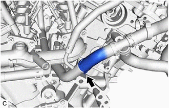
Slide the clip and remove the water by-pass hose assembly from the water inlet pipe.
16267
6.REMOVE NO. 3 WATER BY-PASS HOSE
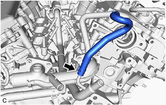
Slide the clip and remove the No. 3 water by-pass hose from the water inlet pipe.
16264
7.REMOVE NO. 2 WATER BY-PASS HOSE
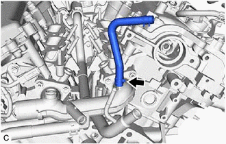
Slide the clip and remove the No. 2 water by-pass hose from the water outlet.
12261
8.REMOVE VENTILATION HOSE
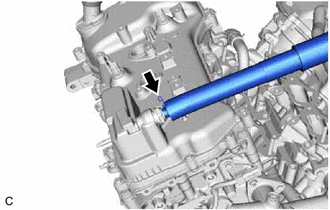
Slide the clip and remove the ventilation hose from the PCV valve (ventilation valve sub-assembly).
12262
9.REMOVE NO. 2 VENTILATION HOSE
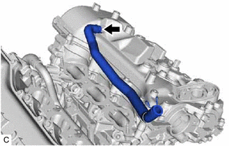
Slide the clip and remove the No. 2 ventilation hose from the cylinder head cover sub-assembly.
16361A
10.REMOVE V-RIBBED BELT
27020
11.REMOVE GENERATOR ASSEMBLY
12.REMOVE COMPRESSOR AND MAGNETIC CLUTCH
88431
13.REMOVE NO. 1 COMPRESSOR MOUNTING BRACKET
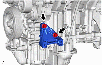
Remove the 2 bolts and No. 1 compressor mounting bracket from the cylinder block sub-assembly.
16604
14.REMOVE NO. 2 IDLER PULLEY SUB-ASSEMBLY
16620
15.REMOVE V-RIBBED BELT TENSIONER ASSEMBLY
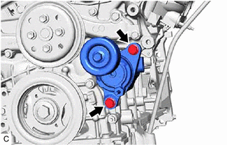
Remove the 2 bolts and V-ribbed belt tensioner assembly.
16173
16.REMOVE WATER PUMP PULLEY
11452
17.REMOVE ENGINE OIL LEVEL DIPSTICK GUIDE
Remove the engine oil level dipstick from the engine oil level dipstick guide.
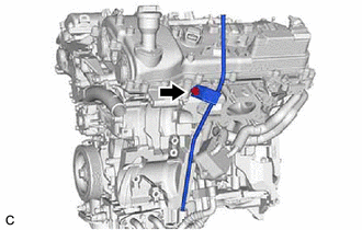
Remove the bolt and engine oil level dipstick guide from the camshaft housing sub-assembly LH and oil pan sub-assembly.
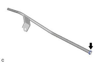
Remove the engine oil level dipstick guide O-ring from the engine oil level dipstick guide.
12585
18.REMOVE NO. 5 CYLINDER BLOCK INSULATOR
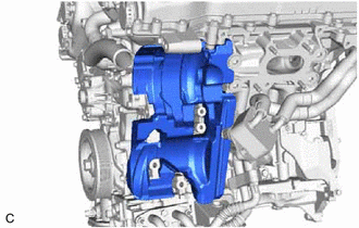
Remove the No. 5 cylinder block insulator from the engine assembly.
43457
19.REMOVE DRIVE SHAFT BEARING BRACKET
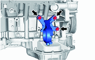
Remove the 3 bolts and drive shaft bearing bracket from the cylinder block sub-assembly.
20.REMOVE WIRE HARNESS CLAMP BRACKET
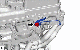
Remove the bolt and wire harness clamp bracket from the camshaft housing sub-assembly LH.
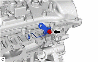
Remove the bolt and wire harness clamp bracket from the camshaft housing sub-assembly.
16522
21.REMOVE WATER FILLER BRACKET
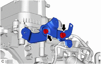
Remove the 2 bolts and water filler bracket from the camshaft housing sub-assembly LH.