P810 HYBRID TRANSMISSION / TRANSAXLE TRANSMISSION CONTROL CABLE INSTALLATION
PROCEDURE

 33820B
1.INSTALL TRANSMISSION CONTROL CABLE ASSEMBLY
- NOTICE:
-
Before installing the transmission control cable assembly, check that the shift lever position sensor and shift lever are in N.
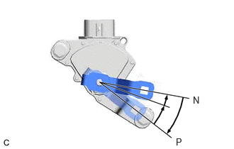
Turn the control shaft lever clockwise until it stops, then turn it counterclockwise 2 notches.
Engage the 2 claws to install a new clip to the transmission control cable assembly.
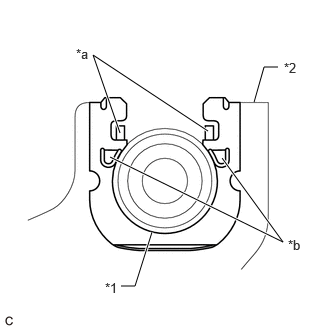
| *1 | Transmission Control Cable Assembly |
| *2 | No. 1 Transmission Control Cable Bracket |
| *a | Claw (A) |
| *b | Claw (B) |
Using a screwdriver, engage the 4 claws and install the transmission control cable assembly to the No. 1 transmission control cable bracket.
- NOTICE:
- ·
Make sure that the claws (A) of the clip are securely engaged in the grooves of the bracket.
·Make sure that the transmission control cable assembly is securely installed inside of the claws (B) of the clip.
Connect the transmission control cable assembly to the control shaft lever with the nut.
- Torque:
- 12 N*m (122 kgf*cm, 9 ft.*lbf)
- NOTICE:
-
Before installing the transmission control cable assembly, check that the shift lever position sensor and shift lever are in N.
Connect the transmission control cable assembly to the inverter with converter assembly with the 2 bolts.
- Torque:
- 12 N*m (122 kgf*cm, 9 ft.*lbf)
Pass the transmission control cable assembly into the vehicle and install the transmission control cable assembly to the vehicle body with the 2 nuts.
- Torque:
- 6.0 N*m (61 kgf*cm, 53 in.*lbf)
Connect the transmission control cable assembly to the vehicle body with the nut.
- Torque:
- 6.0 N*m (61 kgf*cm, 53 in.*lbf)
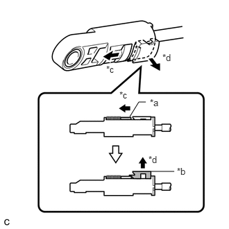
| *a | Slider |
| *b | Lock Piece |
| *c | Slide |
| *d | Pull |
Slide the slider of the transmission control cable assembly in the direction indicated by the arrow in the illustration and pull the lock piece outward.
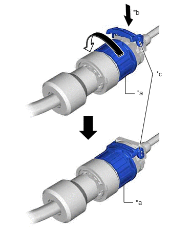
| *a | Lock Nut |
| *b | Push in |
| *c | Stopper |
Turn the lock nut of the transmission control cable assembly counterclockwise. While holding the lock nut, push in the stopper.
- NOTICE:
-
Do not turn the lock nut of the transmission control cable assembly excessively as the internal spring may come off and the transmission control cable assembly will not be reusable.
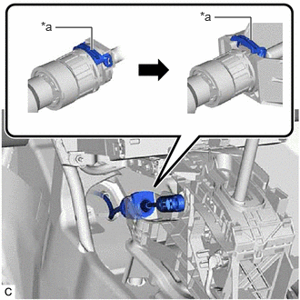
| *a | Stopper |
Connect the transmission control cable assembly to the transmission floor shift assembly.
- NOTICE:
- ·
Install the transmission control cable assembly with the stopper facing upwards.
·After installation, check that the outer part of the stopper is as shown in the illustration.
·Make sure that the transmission control cable assembly is securely locked.
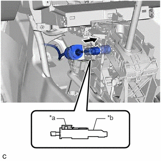
| *a | Lock Piece |
| *b | Adjuster Case |
Connect the transmission control cable assembly to the transmission floor shift assembly.
- NOTICE:
- ·
Check that the lock piece is pulled out.
·Push the end of the transmission control cable assembly all the way to the base of the transmission floor shift assembly pin.
·Connect the transmission control cable assembly so that the lock piece faces the driver side.
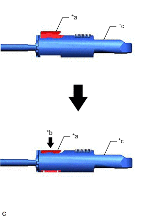
| *a | Lock Piece |
| *b | Push in |
| *c | Adjuster Case |
Push the lock piece into the adjuster case.
- NOTICE:
- ·
Check that the shift lever is in N.
·Securely push in the lock piece until the slider lock is engaged.
·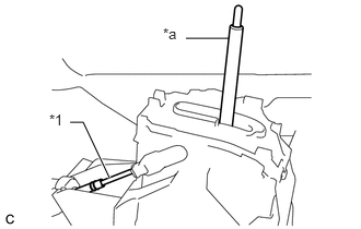 1.771,0.365 2.177,0.365 false 0.667,1.167 0.792,1.167 0.792,1.167 1.042,1.698 true 0.469,1.063 0.708,1.333 0.24,0.271 10 false *1 1.552,0.24 1.875,0.479 0.323,0.24 10 false *a
*1 Transmission Control Cable Assembly *a Lever Shaft
When pushing in the lock piece of the adjuster case to lock it, remove your hand from the lever shaft.
·When pushing in the lock piece of the adjuster case to lock it, do not move the lever shaft or transmission control cable assembly forward or backward.
After adjusting the shift lever position, check the position and operation of the shift lever. If there is a problem, adjust the shift lever position again.
58816B
2.INSTALL FRONT CONSOLE BOX INSERT
55606
3.INSTALL NO. 1 INSTRUMENT PANEL UNDER COVER SUB-ASSEMBLY
55446A
4.INSTALL NO. 1 SWITCH HOLE BASE
5.INSTALL CONSOLE BOX ASSEMBLY
82111
6.CONNECT ENGINE ROOM MAIN WIRE
82121
7.CONNECT ENGINE WIRE
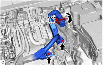
Engage the clamp.
Connect the engine wire with the 2 bolts.
- Torque:
- 10 N*m (102 kgf*cm, 7 ft.*lbf)
Connect the ECM connector and rotate the lever to lock it.
- NOTICE:
- ·
When connecting the ECM connector, make sure that the connecting parts of the ECM connector is free of dirt, water and other foreign matter.
·Be sure to securely connect the ECM connector.
8.INSTALL AIR CLEANER ASSEMBLY WITH AIR CLEANER HOSE
17750A
9.INSTALL INLET AIR CLEANER ASSEMBLY
53295E
10.INSTALL COOL AIR INTAKE DUCT SEAL
12601B
11.INSTALL NO. 1 ENGINE COVER SUB-ASSEMBLY
12.INSPECT SHIFT LEVER POSITION
13.ADJUST SHIFT LEVER POSITION