BRAKE SYSTEM (OTHER) BRAKE BOOSTER(for Gasoline Model RHD) REMOVAL
CAUTION / NOTICE / HINT
The necessary procedures (adjustment, calibration, initialization or registration) that must be performed after parts are removed and installed, or replaced during brake booster assembly removal/installation are shown below.
| Replaced Part or Performed Procedure | Necessary Procedure | Effect/Inoperative Function when Necessary Procedure not Performed | Link |
|---|---|---|---|
|
*: Learning can also be performed using the GTS. Click here( |
|||
| Battery terminal is disconnected/reconnected | Idle the engine for approximately 5 to 60 minutes or drive the vehicle until stop and start control is permitted | Stop and Start System | ( ) |
| Perform steering sensor zero point calibration | Lane Control System | ()
|
|
| Parking Support Brake System* | |||
| Pre-collision System | |||
| Memorize steering angle neutral point | Parking Assist Monitor System | ()
|
|
| Panoramic View Monitor System | ()
|
||
| Initialize back door lock | Power Door Lock Control System | ()
|
|
| Reset back door close position | Power Back Door System | ()
|
|
- NOTICE:
- ·
After the ignition switch is turned off, the radio and display receiver assembly or the radio receiver assembly records various types of memory and settings. As a result, after turning the ignition switch off, make sure to wait at least 120 seconds before disconnecting the cable from the negative (-) battery terminal.
·Make sure to release vacuum from the brake booster assembly before removing the brake master cylinder sub-assembly from the brake booster assembly.
PROCEDURE

 1. RECOVER REFRIGERANT FROM REFRIGERATION SYSTEM
2.REMOVE WINDSHIELD WIPER MOTOR AND LINK ASSEMBLY
53808A
3.REMOVE FENDER SPLASH SHIELD SUB-ASSEMBLY REAR LH
53807A
4.REMOVE FENDER SPLASH SHIELD SUB-ASSEMBLY REAR RH
- HINT:
-
Perform the same procedure as for the LH side.
53892C
5.REMOVE FRONT FENDER SPLASH SHIELD SEAL FRONT LH
53891C
6.REMOVE FRONT FENDER SPLASH SHIELD SEAL FRONT RH
- HINT:
-
Perform the same procedure as for the LH side.
7.REMOVE FRONT UPPER SUSPENSION TO COWL BRACE SUB-ASSEMBLY LH
53607B
8.REMOVE FRONT UPPER SUSPENSION TO COWL BRACE SUB-ASSEMBLY RH
- HINT:
-
Perform the same procedure as for the LH side.
55704B
9.REMOVE COWL VENTILATOR PANEL SUB-ASSEMBLY
67913
10.REMOVE FRONT DOOR SCUFF PLATE RH
- HINT:
-
Use the same procedure as for the LH side.
-
Click hereVehicle Interior>INTERIOR PANELS / TRIM>ROOF HEADLINING>REMOVAL
62111A
11.REMOVE COWL SIDE TRIM SUB-ASSEMBLY RH
- HINT:
-
Use the same procedure as for the LH side.
-
Click hereVehicle Interior>INTERIOR PANELS / TRIM>ROOF HEADLINING>REMOVAL
55606
12.REMOVE NO. 1 INSTRUMENT PANEL UNDER COVER SUB-ASSEMBLY
53601
13.DISCONNECT HOOD LOCK CONTROL LEVER SUB-ASSEMBLY
55045
14.REMOVE LOWER INSTRUMENT PANEL FINISH PANEL SUB-ASSEMBLY
55446A
15.REMOVE NO. 1 SWITCH HOLE BASE
73900
16.REMOVE LOWER NO. 1 INSTRUMENT PANEL AIRBAG ASSEMBLY
17.LOOSEN LOCK NUT
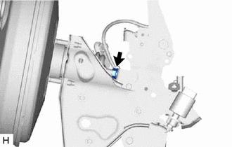
Loosen the lock nut of the brake master cylinder push rod clevis.
47264A
18.REMOVE PUSH ROD PIN
19.DRAIN BRAKE FLUID
47234L
20.DISCONNECT NO. 1 RESERVOIR HOSE
21.REMOVE BRAKE MASTER CYLINDER SUB-ASSEMBLY
47201B
22.REMOVE BRAKE MASTER CYLINDER O-RING
47202
23.REMOVE BRAKE MASTER CYLINDER RESERVOIR SUB-ASSEMBLY
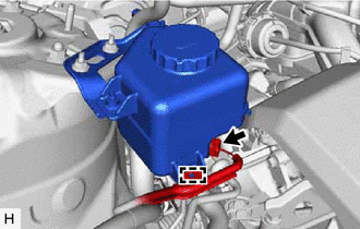
Disconnect the engine room main wire from the brake master cylinder reservoir sub-assembly.
Disengage the clamp to separate the engine room main wire from the brake master cylinder reservoir sub-assembly.
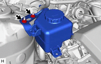
Remove the 2 nuts and brake master cylinder reservoir sub-assembly.
88710G
24.SEPARATE NO. 2 AIR CONDITIONING TUBE AND ACCESSORY ASSEMBLY
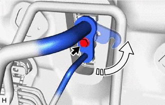

|
Rotate in this Direction |
Remove the bolt and rotate the hook connector as shown in the illustration.
Disconnect the No. 2 air conditioning tube and accessory assembly from the air conditioning unit assembly.
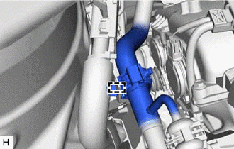
Disengage the clamp to separate the No. 2 air conditioning tube and accessory assembly.
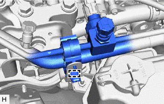
Disengage the clamp to separate the No. 2 air conditioning tube and accessory assembly.
Remove the 2 O-rings from the No. 2 air conditioning tube and accessory assembly.
- NOTICE:
-
Seal the openings of the disconnected parts using vinyl tape to prevent entry of moisture and foreign matter.
82111
25.SEPARATE ENGINE ROOM MAIN WIRE
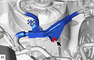
Remove the nut and disengage the clamp to separate the engine room main wire.
47371B
26.REMOVE NO. 6 BRAKE TUBE CLAMP
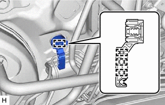
Disengage the 4 clamps to remove the No. 6 brake tube clamp.
47371M
27.SEPARATE NO. 13 BRAKE TUBE CLAMP
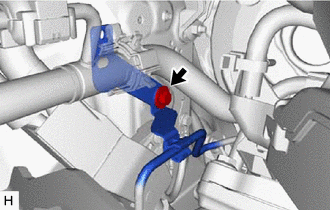
Remove the bolt to separate the No. 13 brake tube clamp from the vehicle body.
44773F
28.DISCONNECT UNION TO CHECK VALVE HOSE
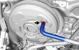
Slide the clip and disconnect the union to check valve hose from the brake booster assembly.
44610
29.REMOVE BRAKE BOOSTER ASSEMBLY
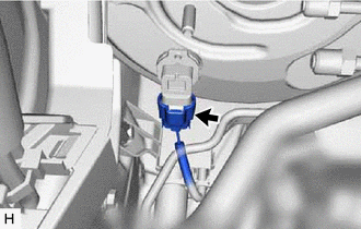
Disconnect the vacuum sensor assembly connector.
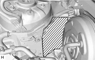

|
Protective Tape |
Apply protective tape to the vehicle body as shown in the illustration.
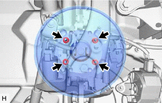
Remove the 4 nuts and push the brake booster assembly toward the engine compartment.
- NOTICE:
-
Do not apply excessive force to the brake lines.
Remove the brake master cylinder push rod clevis and lock nut from the brake booster assembly.
Remove the brake booster assembly from the vehicle body.
- NOTICE:
-
Do not apply excessive force to the brake lines.
- HINT:
-
Remove the brake booster assembly while avoiding the brake lines etc.
44785
30.REMOVE BRAKE BOOSTER GASKET