HYBRID / BATTERY CONTROL HYBRID VEHICLE CONTROL ECU REMOVAL
CAUTION / NOTICE / HINT
The necessary procedures (adjustment, calibration, initialization or registration) that must be performed after parts are removed and installed, or replaced during hybrid vehicle control ECU removal/installation are shown below.
| Replaced Part or Performed Procedure | Necessary Procedure | Effect/Inoperative Function when Necessary Procedure not Performed | Link |
|---|---|---|---|
|
*1: Learning can also be performed using the GTS. Click here( |
|||
| Disconnect cable from negative battery terminal | Perform steering sensor zero point calibration | Lane control system | ( ) |
| Parking Support Brake System*1 | |||
| Pre-collision system | |||
| Memorize steering angle neutral point | Parking assist monitor system | ()
|
|
| Panoramic view monitor system | ()
|
||
| Initialize back door lock | Power Door Lock Control System | ()
|
|
| Reset back door close position | Power Back Door System | ()
|
|
| Replacement of hybrid vehicle control ECU | Code registration | ·
Wireless Door Lock Control System ·
Entry and Start System (for Entry function) ·
Entry and Start System (for start function, HV model) ·
Hybrid control system cannot be started |
See Service Bulletin for the registration method |
- NOTICE:
-
After the ignition switch is turned off, the radio and display receiver assembly or the radio receiver assembly records various types of memory and settings. As a result, after turning the ignition switch off, make sure to wait at least 120 seconds before disconnecting the cable from the negative (-) auxiliary battery terminal.
PROCEDURE

 58441L
1.REMOVE BATTERY SERVICE HOLE COVER
2.DISCONNECT CABLE FROM NEGATIVE AUXILIARY BATTERY TERMINAL
73900
3.REMOVE LOWER NO. 1 INSTRUMENT PANEL AIRBAG ASSEMBLY (for LHD)
55308B
4.REMOVE NO. 3 INSTRUMENT PANEL TO COWL BRACE SUB-ASSEMBLY (for LHD)
55607
5.REMOVE NO. 2 INSTRUMENT PANEL UNDER COVER SUB-ASSEMBLY (for RHD)
- HINT:
-
Use the same procedure for the RHD and LHD.
-
Click hereVehicle Interior>INTERIOR PANELS / TRIM>INSTRUMENT PANEL SAFETY PAD>REMOVAL
55303B
6.REMOVE LOWER INSTRUMENT PANEL SUB-ASSEMBLY (for RHD)
- HINT:
-
Use the same procedure for the RHD and LHD.
-
Click hereVehicle Interior>INTERIOR PANELS / TRIM>INSTRUMENT PANEL SAFETY PAD>REMOVAL
82878
7.REMOVE ECU INTEGRATION BOX LH (for LHD)
Disconnect each connector.
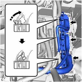
Disconnect the 3 hybrid vehicle control ECU connectors as shown in the illustration.
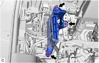
Remove the nut, 2 bolts and ECU integration box LH.
89981
8.REMOVE HYBRID VEHICLE CONTROL ECU (for LHD)
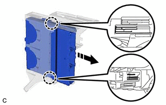
Disengage the 2 claws and remove the hybrid vehicle control ECU from the ECU integration box LH.
- NOTICE:
- ·
If the ECU integration box LH is deformed or damaged, replace it.
·Do not bend the 2 claws more than necessary.
89981
9.REMOVE HYBRID VEHICLE CONTROL ECU (for RHD)
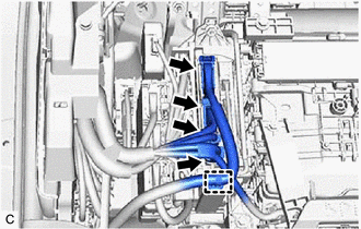
Disconnect each connector.
Disengage the clamp.
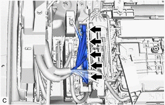
Disconnect each connector.
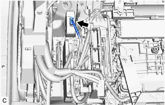
Disconnect the vehicle approaching speaker controller connector.
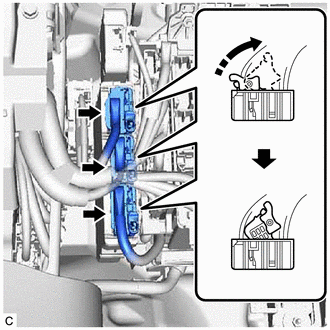
Disconnect the 3 hybrid vehicle control ECU connectors as shown in the illustration.
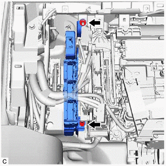
Remove the nut, bolt and hybrid vehicle control ECU.
86572
10.REMOVE VEHICLE APPROACHING SPEAKER CONTROLLER (for RHD)