EXTERIOR PANELS / TRIM REAR BUMPER REMOVAL
CAUTION / NOTICE / HINT
The necessary procedures (adjustment, calibration, initialization, or registration) that must be performed after parts are removed and installed, or replaced during rear bumper assembly removal/installation are shown below.
| Replaced Part or Performed Procedure | Necessary Procedure | Effect/Inoperative Function When Necessary Procedures are not Performed | Link |
|---|---|---|---|
|
*: Even when not replacing the part, it is necessary to perform the specified necessary procedures after installation. |
|||
| Rear bumper assembly* | ·
Measurement of ultrasonic sensor detection angle ·
Ultrasonic sensor detection angle registration |
Parking Support Brake System | ( ) |
| Replaced Part or Performed Procedure | Necessary Procedure | Effect/Inoperative Function When Necessary Procedures are not Performed | Link |
|---|---|---|---|
|
*: Even when not replacing the part, it is necessary to perform the specified necessary procedures after installation. |
|||
| Rear bumper assembly* | ·
Measurement of ultrasonic sensor detection angle ·
Ultrasonic sensor detection angle registration |
Parking Support Brake System | ()
|
- HINT:
-
If the rear bumper assembly is damaged, there is a possibility that the installation area of the blind spot monitor sensor may be deformed and the blind spot monitor system may not operate correctly. Visually inspect the blind spot monitor sensor installation area (vehicle body, stud bolts) to make sure it is not damaged.
-
Click hereAudio / Visual / Telematics>PARK ASSIST / MONITORING>BLIND SPOT MONITOR SENSOR>ADJUSTMENT
-
If damage is found in the visual inspection, check the installation condition of the blind spot monitor sensor, and adjust the installation position of the blind spot monitor sensor as necessary.
PROCEDURE

 1. PRECAUTION (w/ Kick Sensor)
- NOTICE:
-
After turning the ignition switch off, waiting time may be required before disconnecting the cable from the negative (-) auxiliary battery terminal. Therefore, make sure to read the disconnecting the cable from the negative (-) auxiliary battery terminal notices before proceeding with work.
58441L
2.REMOVE BATTERY SERVICE HOLE COVER (w/ Kick Sensor)
for HV Model:
Click hereGeneral>MAINTENANCE>A25A-FXS, A25B-FXS AUXILIARY BATTERY>REMOVAL
3.DISCONNECT CABLE FROM NEGATIVE AUXILIARY BATTERY TERMINAL (w/ Kick Sensor)
for 2GR-FKS:
Click hereGeneral>MAINTENANCE>2GR-FKS BATTERY>REMOVAL
for A25A-FXS, A25B-FXS:
Click hereGeneral>MAINTENANCE>A25A-FXS, A25B-FXS AUXILIARY BATTERY>REMOVAL
76626D
4.REMOVE REAR QUARTER PANEL MUDGUARD LH
76625D
5.REMOVE REAR QUARTER PANEL MUDGUARD RH
- HINT:
-
Use the same procedure as for the LH side.
75874
6.DISCONNECT QUARTER PANEL WHEEL OPENING MOULDING LH
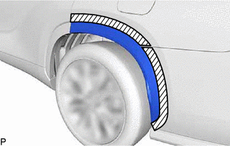

|
Protective Tape |
Apply protective tape around the quarter panel wheel opening moulding LH as shown in the illustration.
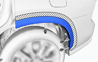
Remove the 3 clips.
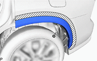
Remove the screw.
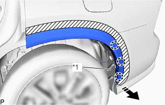
| *1 | Rear Bumper Side Seal LH |

|
Remove in this Direction |
While pulling the rear bumper assembly, insert a finger between the rear bumper side seal LH and rear bumper assembly and disengage the 3 claws as shown in the illustration.
- NOTICE:
- ·
Do not apply excessive force when pulling back the rear bumper side seal LH.
·To avoid damaging the claws, do not forcibly pull the quarter panel wheel opening moulding.
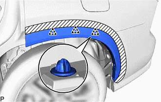
Disengage the 3 clips to disconnect the quarter panel wheel opening moulding LH.
Remove the 3 clips from the quarter panel wheel opening moulding LH.
75873
7.DISCONNECT QUARTER PANEL WHEEL OPENING MOULDING RH
- HINT:
-
Use the same procedure as for the LH side.
81498
8.REMOVE REAR COMBINATION LIGHT COVER LH
81497
9.REMOVE REAR COMBINATION LIGHT COVER RH
- HINT:
-
Use the same procedure as for the LH side.
10.REMOVE REAR BUMPER ASSEMBLY
|
|
Protective Tape |
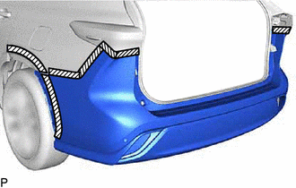
Apply protective tape around the rear bumper assembly as shown in the illustration.
- HINT:
-
Use the same procedure for the RH side and LH side.

|
Screw |

|
Clip |
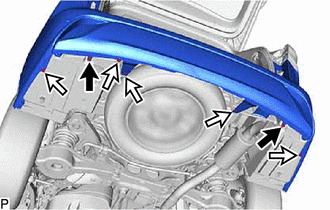
Remove the 2 screws.
Remove the 5 clips.
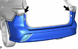
Remove the 2 screws.
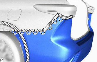
Disengage the 8 claws.
- HINT:
-
Use the same procedure for the RH side and LH side.
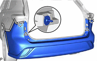
Disengage the 2 claws and 2 clips to remove the rear bumper assembly.
Disconnect each connector.