INSTALLATION
Removal / installation · Vehicles built Aug 2012 – Jul 2013
Versions by build date: Jun 2011 – Jul 2012 Aug 2012 – Jul 2013 from Aug 2013
| 1.
INSPECT TORQUE CONVERTER CLUTCH ASSEMBLY |
 |
Inspect torque converter clutch assembly (Click here).
| 2.
INSTALL TORQUE CONVERTER CLUTCH ASSEMBLY |
|
Install the torque converter clutch to the automatic transmission.
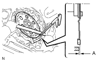
Using a vernier caliper and straightedge, measure dimension A between the transmission and the end surface of the drive plate.
- Standard:
- A = 22.28 mm (0.8772 in.)
Using a vernier caliper and straightedge, measure dimension B shown in the illustration. Check that B is greater than A.
- Standard:
- B = A + 1.00 mm (0.0394 in.) or more
| 3.
INSTALL AUTOMATIC TRANSMISSION ASSEMBLY |
|
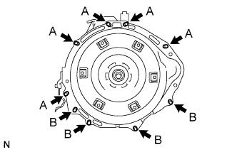
Install the transmission to the engine with the 9 bolts.
-
Torque:
- 71 N*m{
720 kgf*cm
, 53 ft.*lbf
}
for bolt A
- 37 N*m{
380 kgf*cm
, 27 ft.*lbf
}
for bolt B
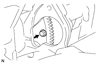
- Hold the crankshaft pulley bolt with a wrench and install the 6 torque converter clutch mounting bolts.
-
Torque:
- 48 N*m{
489 kgf*cm
, 35 ft.*lbf
}
- HINT:
- First install the black bolt, and then the other 5 bolts.
| 4.
INSTALL FLYWHEEL HOUSING SIDE COVER |
|
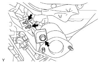
| 5.
INSTALL STARTER ASSEMBLY |
|
Install starter assembly (Click here).
| 7.
CONNECT CONNECTOR |
|
Transmission side:
Connect the connectors.
Connect the park/neutral position switch connector.
Connect the transmission wire connector.
Connect the 2 speed sensor connectors.
Transfer side:
Connect the connectors.
Connect the No. 1 indicator switch connector.
Connect the No. 2 indicator switch connector.
| 8.
INSTALL NO. 1 ENGINE MOUNTING INSULATOR REAR |
|
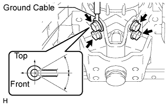
Install the engine mounting insulator and ground cable to the transmission with the 4 bolts.
-
Torque:
- 65 N*m{
663 kgf*cm
, 48 ft.*lbf
}
- HINT:
- The acceptable installation angle of the ground cable is within 30° upward or downward from the horizontal position.
| 9.
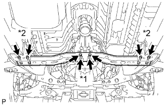
INSTALL NO. 3 FRAME CROSSMEMBER SUB-ASSEMBLY |
|
*1: Install the 4 set bolts of the engine mounting insulator.
-
Torque:
- 27 N*m{
275 kgf*cm
, 20 ft.*lbf
}
*2: Install the frame crossmember with the 4 bolts and 4 nuts.
-
Torque:
- 50 N*m{
510 kgf*cm
, 37 ft.*lbf
}
| 10.
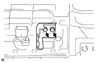
INSTALL NO. 1TRANSMISSION CONTROL CABLE BRACKET |
|
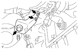
Install the control cable bracket with the 2 bolts.
-
Torque:
- 28 N*m{
286 kgf*cm
, 21 ft.*lbf
}
| 11.
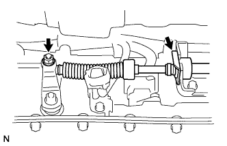
INSTALL TRANSMISSION CONTROL CABLE ASSEMBLY |
|
Connect the control cable with the clip.
Connect the control cable with the nut.
-
Torque:
- 14 N*m{
143 kgf*cm
, 10 ft.*lbf
}
| 12.
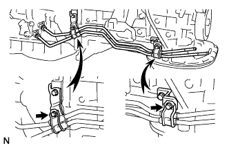
INSTALL OIL COOLER TUBE |
|
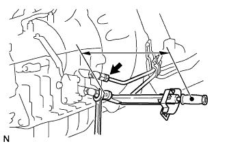
Loosely install the tip of the oil cooler tube inlet to the automatic transmission by hand.
Loosely install the tip of the oil cooler tube outlet to the automatic transmission by hand.
Install the 2 clamps with the 2 bolts.
-
Torque:
- 5.0 N*m{
50 kgf*cm
, 43 in.*lbf
}
- Using SST, tighten the oil cooler inlet and outlet tubes.
-
Torque:
- 34 N*m{
346 kgf*cm
, 25 ft.*lbf
}
- NOTICE:
- Use the formula to calculate special torque values for situations where a union nut wrench is combined with a torque wrench (Click here)
| 13.
INSTALL EXHAUST MANIFOLD SUB-ASSEMBLY RH
|
|
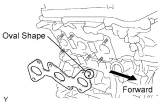
- Set a new gasket to the RH cylinder head with the oval shape facing forward.
- NOTICE:
- Be careful of the installation direction.
Install the exhaust manifold with the 6 nuts. Uniformly tighten the nuts in several passes.
-
Torque:
- 21 N*m{
214 kgf*cm
, 15 ft.*lbf
}
Connect the A/F sensor connector.
| 14.
INSTALL EXHAUST MANIFOLD SUB-ASSEMBLY LH
|
|
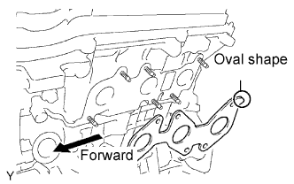
- Set a new gasket to the LH cylinder head with the oval shape facing backward.
- NOTICE:
- Be careful of the installation direction.
Install the exhaust manifold with the 6 nuts. Uniformly tighten the nuts in several passes.
-
Torque:
- 21 N*m{
214 kgf*cm
, 15 ft.*lbf
}
Connect the A/F sensor connector.
| 15.
INSTALL NO. 2 MANIFOLD STAY |
|
Install the manifold stay with the 3 bolts.
-
Torque:
- 40 N*m{
408 kgf*cm
, 30 ft.*lbf
}
| 16.
INSTALL MANIFOLD STAY |
|
Install the manifold stay with the 3 bolts.
-
Torque:
- 40 N*m{
408 kgf*cm
, 30 ft.*lbf
}
| 17.
INSTALL PROPELLER SHAFT WITH CENTER BEARING ASSEMBLY |
|
for TMT Made:
Install the propeller shaft with center bearing assembly (Click here).
for TSAM Made:
Install the propeller shaft with center bearing assembly (Click here).
| 18.
INSTALL EXHAUST PIPE |
|
Install the exhaust pipe (Click here).
| 19.
CONNECT OXYGEN SENSOR |
|
| 20.
INSTALL NO.2 FRAME CROSSMEMBER SUB-ASSEMBLY (except Pre-Runner) |
|
Install the frame crossmember with the 4 bolts and 4 nuts.
-
Torque:
- 50 N*m{
510 kgf*cm
, 37 ft.*lbf
}
| 21.
CONNECT CABLE TO NEGATIVE BATTERY TERMINAL |
|
| 22.
ADD AUTOMATIC TRANSMISSION FLUID |
|
Add automatic transmission fluid (Click here).
| 23.
ADJUST AUTOMATIC TRANSMISSION FLUID |
|
Adjust the automatic transmission fluid (Click here).
| 24.
INSPECT SHIFT LEVER POSITION |
|
Inspect the shift lever position (Click here).
| 25.
PERFORM INITIALIZATION |
|
Perform initialization (Click here).
- NOTICE:
- Certain systems need to be initialized after disconnecting and reconnecting the cable from the negative (-) battery terminal.
| 26.
CHECK FOR EXHAUST GAS LEAKS |
|
| 27.
INSTALL NO.3 ENGINE UNDER COVER (for Pre-Runner) |
|
-
Torque:
- 28 N*m{
286 kgf*cm
, 21 ft.*lbf
}
| 28.
INSTALL NO.2 ENGINE UNDER COVER (for Pre-Runner) |
|
-
Torque:
- 28 N*m{
286 kgf*cm
, 21 ft.*lbf
}
| 29.
INSTALL NO.1 ENGINE UNDER COVER |
|
-
Torque:
- 28 N*m{
286 kgf*cm
, 21 ft.*lbf
}