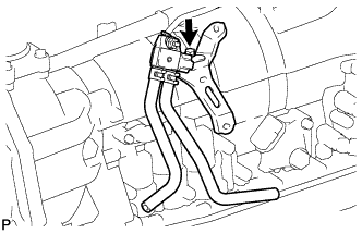
REMOVAL
Removal / installation · Vehicles built Aug 2012 – Jul 2013
Versions by build date: Jun 2011 – Jul 2012 Aug 2012 – Jul 2013 from Aug 2013
| 1. DISCONNECT CABLE FROM NEGATIVE BATTERY TERMINAL |

- NOTICE:
- When disconnecting the cable, some systems need to be initialized after the cable is reconnected (Click here).
| 2. REMOVE SHIFT LEVER KNOB SUB-ASSEMBLY |
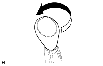  |
Twist the shift lever knob in the direction indicated by the arrow and remove it.
| 3. REMOVE PARKING BRAKE HOLE COVER SUB-ASSEMBLY |
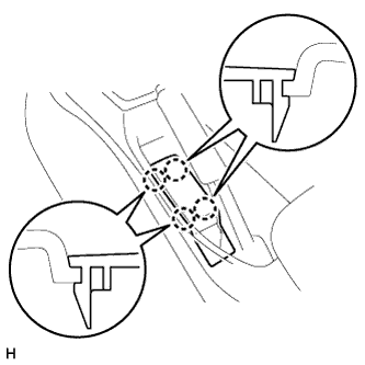 |
Detach the 4 claws and remove the parking brake hole cover.
| 4. REMOVE UPPER CONSOLE PANEL SUB-ASSEMBLY |
Detach the 12 claws and remove the upper console panel.
- NOTICE:
- Be careful not to damage the instrument panel and console box with the claws of the upper console panel.
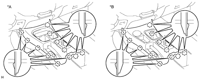
Text in Illustration *A
for 2WD
*B
for 4WD
| 5. REMOVE CONSOLE BOX ASSEMBLY |
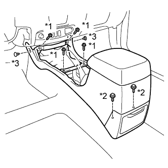 |
Remove the 4 screws and 2 bolts.
Using a clip remover, remove the 2 clips and console box.
Text in Illustration *1
Screw
*2
Bolt
*3
Clip
| 6. REMOVE SHIFT LEVER BOOT ASSEMBLY |
Remove the 4 screws and shift lever boot.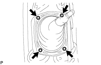
| 7. REMOVE TRANSFER HIGH AND LOW SHIFT LEVER ASSEMBLY |
Fold back the transfer front drive shift boot.
Using needle-nose pliers, remove the snap ring and pull out the shift lever.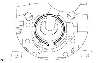
- HINT:
- Move the transfer shift lever to the H4 position.
| 8. REMOVE NO. 1 ENGINE UNDER COVER |
| 9. REMOVE NO. 2 ENGINE UNDER COVER |
| 10. REMOVE FRONT EXHAUST PIPE ASSEMBLY |
for DPF:
Remove the front exhaust pipe assembly (Click here).
except DPF:
Remove the front exhaust pipe assembly (Click here).
| 11. REMOVE NO. 2 EXHAUST MANIFOLD HEAT INSULATOR (for DPF) |
Remove the 2 bolts and No. 2 exhaust manifold heat insulator.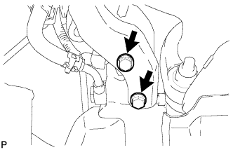
| 12. REMOVE NO. 3 EXHAUST MANIFOLD HEAT INSULATOR (for DPF) |
Remove the 2 bolts and No. 3 exhaust manifold heat insulator.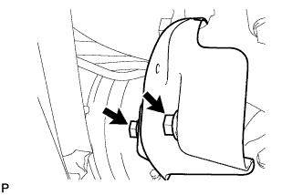
| 13. REMOVE TURBINE OUTLET ELBOW STAY (for DPF) |
Detach the wire harness clamp and remove the bolt, nut and turbine outlet elbow stay.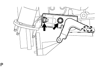
| 14. REMOVE NO. 2 TURBINE OUTLET ELBOW (for DPF) |
Remove the 3 nuts, No. 2 turbine outlet elbow and gasket.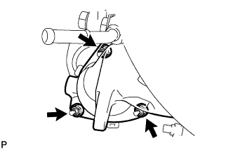
| 15. REMOVE FRONT PROPELLER SHAFT ASSEMBLY |
for TMT Made:
Remove the front propeller shaft assembly (Click here).
for TSAM Made:
Remove the front propeller shaft assembly (Click here).
| 16. REMOVE PROPELLER SHAFT WITH CENTER BEARING ASSEMBLY |
for TMT Made:
Remove the front propeller shaft assembly (Click here).
for TSAM Made:
Remove the front propeller shaft assembly (Click here).
| 17. DRAIN AUTOMATIC TRANSMISSION FLUID |
Remove the drain plug and gasket, and drain the ATF.
Install a new gasket and the drain plug.
- Torque:
- 20 N*m{ 204 kgf*cm , 15 ft.*lbf }
| 18. DISCONNECT OIL COOLER TUBE |
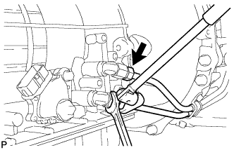 |
Using a union nut wrench, disconnect the tube outlet and tube inlet.
Remove the 3 bolts and 3 clamps.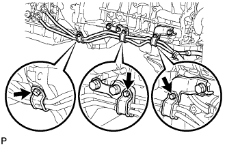
| 19. DISCONNECT TRANSMISSION CONTROL CABLE ASSEMBLY |
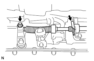 |
Remove the nut and clip and disconnect the control cable.
| 20. REMOVE NO. 1 TRANSMISSION CONTROL CABLE BRACKET |
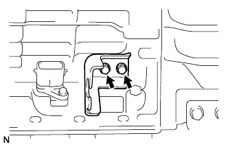 |
Remove the 2 bolts and control cable bracket from the transmission.
| 21. SUPPORT AUTOMATIC TRANSMISSION ASSEMBLY |
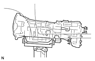 |
Support the transmission with a transmission jack.
| 22. REMOVE NO. 3 FRAME CROSSMEMBER SUB-ASSEMBLY |
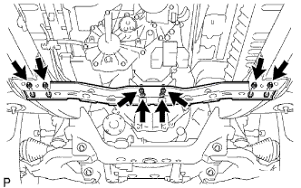 |
Remove the 4 set bolts of the rear No. 1 engine mounting insulator.
Remove the 4 nuts, 4 bolts and frame crossmember.
| 23. REMOVE REAR NO. 1 ENGINE MOUNTING INSULATOR |
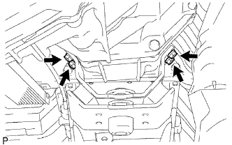 |
Remove the 4 bolts and rear No. 1 engine mounting insulator from the automatic transmission.
| 24. DISCONNECT WIRE HARNESS |
Remove the nut and disconnect the ground cable.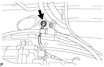
Tilt the transmission downward.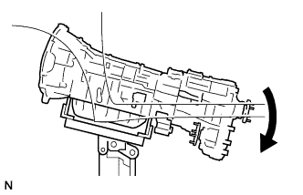
- NOTICE:
- Make sure the cooling fan does not contact the fan shroud.
except DPF:
Disconnect the park/neutral position switch connector.
Disconnect the transmission wire connector.
Disconnect the 2 speed sensor connectors.
Disconnect the No. 1 indicator switch connector.
Disconnect the No. 2 indicator switch connector.
Disconnect the No. 3 indicator switch connector.
Disconnect the speed sensor connector.
Detach the 7 clamps.
Remove the bolt and disconnect the wire harness.
for DPF:
Disconnect the park/neutral position switch connector.
Disconnect the transmission wire connector.
Disconnect the 2 speed sensor connectors.
Disconnect the differential pressure sensor connector.
Disconnect the No. 1 indicator switch connector.
Disconnect the No. 2 indicator switch connector.
Disconnect the No. 3 indicator switch connector.
Disconnect the speed sensor connector.
Detach the 10 clamps.
Remove the bolt and disconnect the wire harness.
| 25. REMOVE STARTER ASSEMBLY |
for 2.2 kW Type:
Remove the starter assembly (Click here).
for 2.7 kW Type:
Remove the starter assembly (Click here).
| 26. REMOVE STIFFENER PLATE |
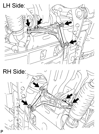 |
Remove the 4 bolts and stiffener plate RH (with oil cooler tube clamp).
Remove the 4 bolts and stiffener plate LH.
Remove the No. 4 cylinder block insulator.
Remove the end plate.
| 27. REMOVE AUTOMATIC TRANSMISSION ASSEMBLY |
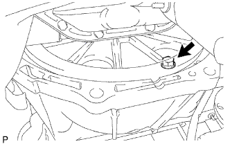 |
Turn the crankshaft to gain access to the 6 torque converter clutch setting bolts and remove each bolt through the hole of the flywheel while holding the crankshaft pulley bolt with a wrench.
Remove the 5 bolts.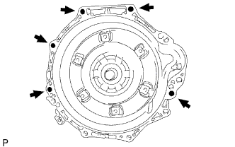
Remove the automatic transmission assembly.
| 28. REMOVE TRANSFER ASSEMBLY |
Remove the transfer assembly (Click here).
| 29. REMOVE TORQUE CONVERTER CLUTCH ASSEMBLY |
Remove the torque converter clutch assembly from the automatic transmission assembly.
| 30. REMOVE DIFFERENTIAL PRESSURE SENSOR (for DPF) |
Remove the bolt and sensor bracket.