2TR-FE ENGINE MECHANICAL CAMSHAFT REMOVAL
PROCEDURE

 1. PRECAUTION
- NOTICE:
-
After turning the ignition switch off, waiting time may be required before disconnecting the cable from the battery terminal. Therefore, make sure to read the disconnecting the cable from the battery terminal notice before proceeding with work (See page General>INTRODUCTION>REPAIR INSTRUCTION>PRECAUTION).
2.DISCONNECT CABLE FROM NEGATIVE BATTERY TERMINAL
- NOTICE:
-
When disconnecting the cable, some systems need to be initialized after the cable is reconnected (See page General>INTRODUCTION>REPAIR INSTRUCTION>INITIALIZATION).
3.REMOVE FAN AND GENERATOR V BELT
4.REMOVE INTAKE AIR CONNECTOR
5.REMOVE IGNITION COIL ASSEMBLY
6.REMOVE CYLINDER HEAD COVER SUB-ASSEMBLY
7.REMOVE TIMING CHAIN GUIDE
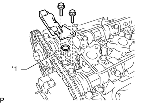
| *1 | O-Ring |
Remove the 2 bolts, chain guide and O-ring.
8.REMOVE CAMSHAFT TIMING SPROCKET
Turn the crankshaft pulley, and align its groove with the "0" timing mark of the timing chain cover.
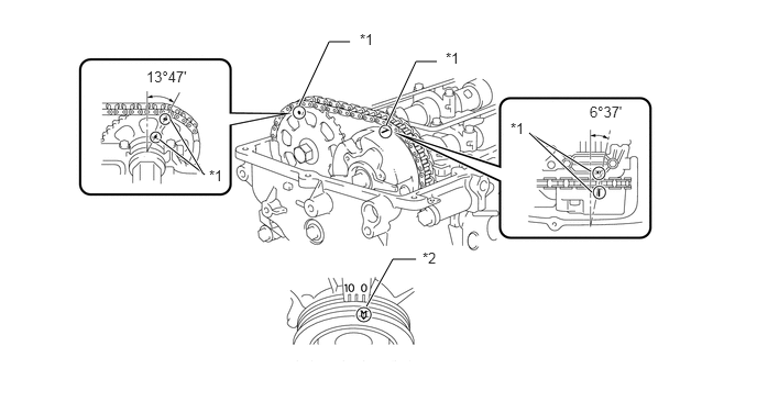
| *1 | Timing Mark | *2 | Groove |
Check that the timing marks of the camshaft timing gear and sprocket are aligned with the timing marks of the No. 1 bearing cap as shown in the illustration.
- HINT:
-
If the timing marks do not align, rotate the crankshaft clockwise again and align the timing marks.
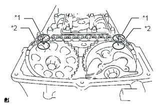
| *1 | Paint Mark |
| *2 | Timing Mark |
Place paint marks on the timing chain, camshaft timing gear and sprocket.
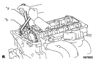
| *a | Hold |
| *b | Loosen |
Hold the camshaft with a wrench and loosen the sprocket bolt.
- NOTICE:
-
Be careful not to damage the oil delivery pipe.
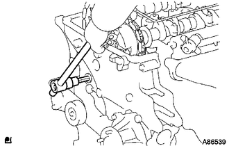
Using a 10 mm socket hexagon wrench, remove the timing chain cover plug.
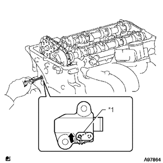
| *1 | Stopper Plate |
Using a screwdriver, access the tensioner stopper plate through the chain tensioner service hole. Move the stopper plate upward to release the lock. Then hold the plate in that position as shown in the illustration.
- HINT:
-
If the lock of the stopper plate is difficult to release, slightly rotate the hexagonal part of the camshaft to the left and right.
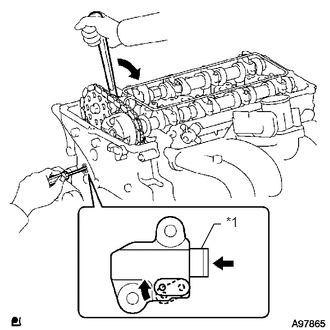
| *1 | Plunger |
With the lock of the stopper plate released, slightly rotate the camshaft clockwise and keep it in that position.
- NOTICE:
-
Be careful not to damage the oil delivery pipe.
- HINT:
-
Rotating the camshaft clockwise will cause pressure to be applied to the tensioner plunger.
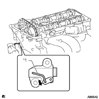
| *1 | Hexagon Wrench |
Remove the screwdriver from the chain tensioner service hole. Move the stopper plate to the position shown in the illustration. Then insert a hexagon wrench into the hole.
- HINT:
- ·
If the wrench cannot fit into the hole, slightly rotate the camshaft counterclockwise, and then clockwise. Then insert the wrench.
·To prevent the wrench from falling out, use tape to fix the wrench in place.
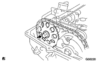
Remove the camshaft timing sprocket from the No. 2 camshaft.
9.REMOVE CAMSHAFT
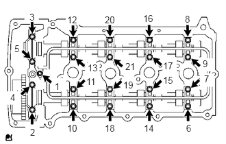
Uniformly loosen the 21 bearing cap bolts in several passes in the sequence shown in the illustration.
Remove the 9 bearing caps, oil delivery pipe, O-ring and No. 2 camshaft.
- NOTICE:
- ·
Uniformly loosen the bolts while keeping the camshafts level.
·Do not pry the camshaft with a tool as an excessive amount of force may be applied to it.
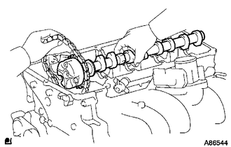
Remove the No. 1 camshaft while holding the timing chain.
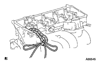
Secure the timing chain with a string as shown in the illustration.
- NOTICE:
-
Be careful not to drop anything inside the timing chain cover.
10.REMOVE NO. 1 VALVE ROCKER ARM SUB-ASSEMBLY
Remove the 16 valve rocker arms from the cylinder head.
- HINT:
-
Arrange the removed parts in the correct order.
11.REMOVE VALVE LASH ADJUSTER ASSEMBLY
Remove the 16 valve lash adjusters from the cylinder head.
- HINT:
-
Arrange the removed parts in the correct order.
12.REMOVE CAMSHAFT TIMING GEAR ASSEMBLY
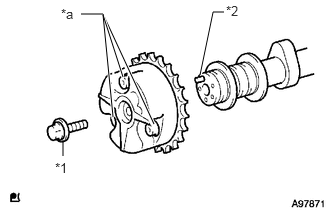
| *1 | Flange Bolt |
| *2 | Straight Pin |
| *a | Do Not Remove |
Remove the flange bolt of the camshaft timing gear.
- NOTICE:
-
Be sure not to remove the other 3 bolts.
13.INSPECT VALVE LASH ADJUSTER ASSEMBLY
14.INSPECT CAMSHAFT TIMING GEAR ASSEMBLY