AXLE AND DIFFERENTIAL STEERING KNUCKLE INSTALLATION
CAUTION / NOTICE / HINT
- HINT:
- ·
Use the same procedure for the RH and LH sides.
·The procedure listed below is for the LH side.
PROCEDURE

 1.INSTALL FRONT AXLE HUB INNER BEARING LH
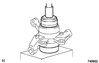
Using SST and a press, press a new bearing into the steering knuckle.
- SST
- 09527-17011
09950-60020 (09951-00910)
Using snap ring pliers, install a new snap ring.
2.INSTALL FRONT AXLE HUB OIL SEAL LH
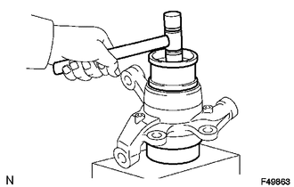
Using SST and a plastic-faced hammer, tap in a new oil seal.
- SST
- 09223-15030
09527-17011
Apply MP grease to the lip of the oil seal.
3.INSTALL STEERING KNUCKLE LH
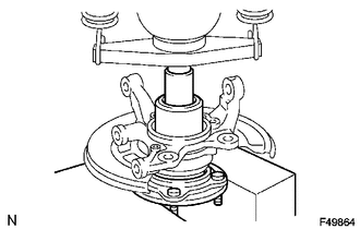
Install the dust cover to the steering knuckle with the 3 bolts.
- Torque:
- 8.0 N*m (82 kgf*cm, 71 ft.*lbf)
Using SST and a press, press the axle hub into the steering knuckle.
- SST
- 09223-00010
4.INSTALL FRONT SKID CONTROL ROTOR
Install the front skid control rotor.
5.INSTALL FRONT AXLE HUB NUT LH
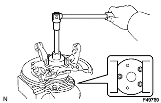
Install a new nut to the axle hub.
- Torque:
- 199 N*m (2029 kgf*cm, 147 ft.*lbf)
Using a chisel and hammer, stake the nut.
- NOTICE:
-
Do not scratch the serration of the speed sensor rotor.
6.INSTALL KNUCKLE GREASE RETAINER CAP LH
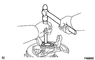
Using a brass bar and hammer, install the knuckle grease retainer cap.
- NOTICE:
-
Do not damage the knuckle grease retainer cap.
7.INSTALL FRONT AXLE HUB ASSEMBLY
Install the front axle hub assembly.
8.CONNECT FRONT UPPER SUSPENSION ARM ASSEMBLY LH
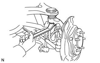
Connect the upper arm with the nut.
- Torque:
- 110 N*m (1122 kgf*cm, 81 ft.*lbf)
Install a new clip.
- NOTICE:
-
If the holes for the clip are not aligned, tighten the nut an additional 60°.
9.CONNECT FRONT LOWER SUSPENSION ARM ASSEMBLY LH
Connect the suspension arm with the 2 bolts.
- Torque:
- 160 N*m (1632 kgf*cm, 118 ft.*lbf)
10.CONNECT TIE ROD END SUB-ASSEMBLY LH
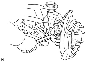
Connect the tie rod end with the nut.
- Torque:
- 49 N*m (500 kgf*cm, 36 ft.*lbf)
Install a new cotter pin.
- NOTICE:
-
If the holes for the cotter pin are not aligned, tighten the nut an additional 60°.
11.INSTALL FRONT DISC
12.INSTALL FRONT DISC BRAKE CYLINDER ASSEMBLY LH
Install the brake cylinder with the 2 bolts.
- Torque:
- 117 N*m (1191 kgf*cm, 86 ft.*lbf)
13.CONNECT FRONT FLEXIBLE HOSE
14.INSTALL FRONT SPEED SENSOR LH
Install the speed sensor with the bolt.
- Torque:
- 8.5 N*m (87 kgf*cm, 75 in.*lbf)
Connect the 3 clamps with the 3 bolts.
- Torque:
- 32 N*m (326 kgf*cm, 24 ft.*lbf)
15.BLEED BRAKE LINE
16.INSTALL FRONT WHEEL
17.CHECK ABS SPEED SENSOR SIGNAL