EXTERIOR PANELS / TRIM BLACK OUT TAPE(for Rear Door) INSTALLATION
CAUTION / NOTICE / HINT
- HINT:
- ·
Use the same procedure for RHD and LHD vehicles.
·The procedure listed below is for LHD vehicles.
·Use the same procedure for the RH and LH sides.
·The procedure listed below is for the LH side.
·A bolt without a torque specification is shown in the standard bolt chart (See page General>SPECIFICATIONS>STANDARD BOLT>SPECIFIED TORQUE FOR STANDARD BOLTS).
PROCEDURE

 1. REPAIR INSTRUCTION
2.INSTALL REAR OUTER BLACK OUT TAPE LH
- HINT:
-
When installing the rear outer black out tape, heat the rear door panel and rear outer black out tape using a heat light.
- Standard:
Item Temperature Rear Door Panel 40 to 60°C (104 to 140°F) Rear Outer Black Out Tape 20 to 30°C (68 to 86°F)
- NOTICE:
-
Do not heat the rear door panel or rear outer black out tape excessively.
Clean the rear door panel surface.
Using a heat light, heat the rear door panel surface.
Remove the double-sided tape from the rear door panel.
Wipe off any tape adhesive residue with cleaner.
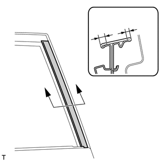
Install a new rear outer black out tape.
Using a heat light, heat the rear door panel and a new rear outer black out tape.
Remove the peeling paper from the face of the rear outer black out tape.
- HINT:
-
After removing the peeling paper, keep the exposed adhesive free from foreign matter.
Install the rear outer black out tape in the position shown in the illustration.
- HINT:
-
Press the rear outer black out tape firmly to install it.
- Standard:
Area Measurement A 2 to 4 mm (0.0787 to 0.157 in.) B 4 to 6 mm (0.157 to 0.236 in.)
3.INSTALL UPPER OUTER BLACK OUT TAPE LH
- HINT:
-
When installing the upper outer black out tape, heat the rear door panel and upper outer black out tape using a heat light.
- Standard:
Item Temperature Rear Door Panel 40 to 60°C (104 to 140°F) Upper Outer Black Out Tape 20 to 30°C (68 to 86°F)
- NOTICE:
-
Do not heat the rear door panel or upper outer black out tape excessively.
Clean the rear door panel surface.
Using a heat light, heat the rear door panel surface.
Remove the double-sided tape from the rear door panel.
Wipe off any tape adhesive residue with cleaner.
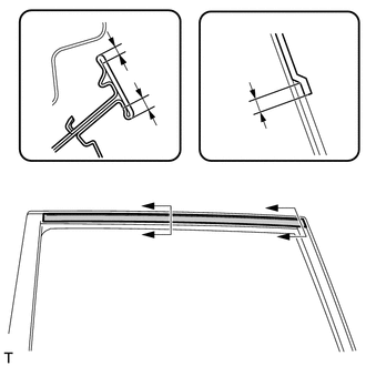
Install a new upper outer black out tape.
Using a heat light, heat the rear door panel and a new upper outer black out tape.
Remove the peeling paper from the face of the upper outer black out tape.
- HINT:
-
After removing the peeling paper, keep the exposed adhesive free from foreign matter.
Install the upper outer black out tape in the position shown in the illustration.
- HINT:
-
Press the upper outer black out tape firmly to install it.
- Standard:
Area Measurement A 2 to 4 mm (0.0787 to 0.157 in.) B 4 to 6 mm (0.157 to 0.236 in.) C 1 to 3 mm (0.0394 to 0.118 in.)
4.INSTALL FRONT OUTER BLACK OUT TAPE LH
- HINT:
-
When installing the front outer black out tape, heat the rear door panel and front outer black out tape using a heat light.
- Standard:
Item Temperature Rear Door Panel 40 to 60°C (104 to 140°F) Front Outer Black Out Tape 20 to 30°C (68 to 86°F)
- NOTICE:
-
Do not heat the rear door panel or front outer black out tape excessively.
Clean the rear door panel surface.
Using a heat light, heat the rear door panel surface.
Remove the double-sided tape from the rear door panel.
Wipe off any tape adhesive residue with cleaner.
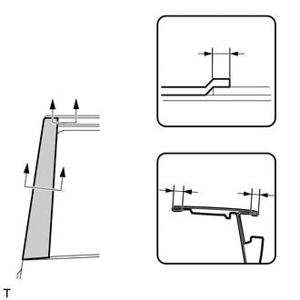
Install a new front outer black out tape.
Using a heat light, heat the rear door panel and a new front outer black out tape.
Remove the peeling paper from the face of the front outer black out tape.
- HINT:
-
After removing the peeling paper, keep the exposed adhesive free from foreign matter.
Install the front outer black out tape in the position shown in the illustration.
- HINT:
-
Press the front outer black out tape firmly to install it.
- Standard:
Area Measurement A 1 to 3 mm (0.0394 to 0.118 in.) B 2 to 4 mm (0.0787 to 0.157 in.) C 4 to 6 mm (0.157 to 0.236 in.)
5.INSTALL REAR DOOR BELT MOULDING ASSEMBLY LH
6.INSTALL REAR DOOR GLASS SUB-ASSEMBLY LH
7.INSTALL REAR DOOR QUARTER WINDOW GLASS LH
8.INSTALL REAR DOOR WINDOW DIVISION BAR SUB-ASSEMBLY LH
9.INSTALL REAR DOOR GLASS RUN LH
10.INSTALL REAR DOOR SERVICE HOLE COVER LH
11.INSTALL REAR DOOR NO. 2 TRIM BRACKET
12.INSTALL REAR DOOR INSIDE HANDLE SUB-ASSEMBLY LH
13.INSTALL REAR DOOR TRIM BOARD SUB-ASSEMBLY LH
14.INSTALL REAR POWER WINDOW REGULATOR SWITCH ASSEMBLY WITH REAR DOOR ARMREST BASE PANEL
15.CONNECT CABLE TO NEGATIVE BATTERY TERMINAL
- NOTICE:
-
When disconnecting the cable, some systems need to be initialized after the cable is reconnected (See page General>INTRODUCTION>REPAIR INSTRUCTION>INITIALIZATION).