2013-2015 Land Cruiser Prado · Service Manual Vehicle Interior

Theft Warning Siren Circuit

Circuit diagnosis · Vehicles built from Aug 2014

Versions by build date: Aug 2013 – Jul 2014 from Aug 2014

DESCRIPTION

  1. The theft warning siren assembly (self power siren) has an internal battery. If the vehicle battery cable is disconnected or any of the communication lines are open, the theft warning siren assembly (self power siren) detects this and sounds its siren.
  2. Although the theft warning siren assembly (self power siren) usually sounds by receiving a signal from the main body ECU, the theft warning siren assembly (self power siren) can sound by its internal battery in case the vehicle battery cable is disconnected.
  3. The main body ECU sends an arming signal to the theft warning siren assembly (self power siren) while switching to the armed state, and it sends a disarming signal to the siren while switching to the disarmed state. Also, the main body ECU can cause the theft warning siren assembly (self power siren) to sound by sending an alarm signal during the alarm sounding state.

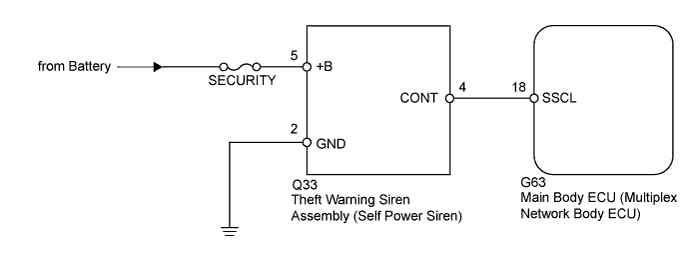
WIRING DIAGRAM

B159044E08

INSPECTION PROCEDURE

NOTICE:
Inspect the fuses for circuits related to this system before performing the following inspection procedure.


1. PERFORM ACTIVE TEST USING INTELLIGENT TESTER (THEFT WARNING SIREN)
  1. Operate the intelligent tester according to the steps on the display and select Active Test (Click here).
    Main Body 
    Tester Display
    Test Part
    Control Range
    Diagnostic Note
    Security Horn2
    Theft warning siren (self power siren)
    ON/OFF
    -

    OK:
    Siren operates normally.


NG
Go to step 2
OK

PROCEED TO NEXT SUSPECTED AREA SHOWN IN PROBLEM SYMPTOMS TABLE (Click here)

2. CHECK HARNESS AND CONNECTOR (THEFT WARNING SIREN - BATTERY AND BODY GROUND)

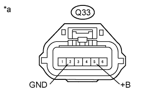
  1. B298276E01
    Disconnect the Q33 siren connector.

  1. Measure the resistance according to the value(s) in the table below.

    Standard Resistance:
    Tester Connection
    Condition
    Specified Condition
    Q33-2 (GND) - Body ground
    Always
    Below 1 Ω

  1. Measure the voltage according to the value(s) in the table below.

    Standard Voltage:
    Tester Connection
    Condition
    Specified Condition
    Q33-5 (+B) - Body ground
    Always
    11 to 14 V

Text in Illustration 
*a
Front view of wire harness connector
(to Theft Warning Siren Assembly)


NG
REPAIR OR REPLACE HARNESS OR CONNECTOR
OK


3. CHECK MAIN BODY ECU (OUTPUT SIGNAL)

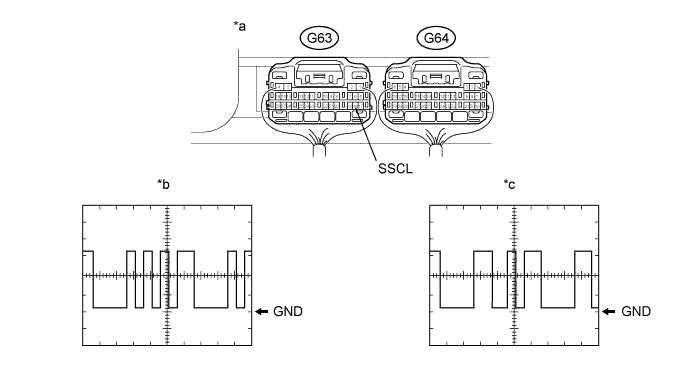
  1. Using an oscilloscope, check waveform 1.B243352E01

    Text in Illustration 
    *a
    Component with harness connected
    (Main Body ECU)
    *b
    Waveform 1
    *c
    Waveform 2
    -
    -
    Measurement Condition 
    Item
    Content
    Tester Connection
    G63-18 (SSCL) - Body ground
    Tool Setting
    2 V/DIV., 20 ms./DIV.
    Condition
    Switched from armed state or arming preparation state to disarmed state

  1. Using an oscilloscope, check waveform 2.

    Measurement Condition 
    Item
    Content
    Tester Connection
    G63-18 (SSCL) - Body ground
    Tool Setting
    2 V/DIV., 20 ms./DIV.
    Condition
    Switched from arming preparation state to armed state

OK:
Waveform is output normally (refer to illustration).


NG
Go to step 4
OK

REPLACE THEFT WARNING SIREN ASSEMBLY (SELF POWER SIREN) (Click here)

4. CHECK HARNESS AND CONNECTOR (THEFT WARNING SIREN - MAIN BODY ECU)
  1. Disconnect the Q33 siren connector.

  1. Disconnect the G63 ECU connector.

  1. Measure the resistance according to the value(s) in the table below.

    Standard Resistance:
    Tester Connection
    Condition
    Specified Condition
    Q33-4 (CONT) - G63-18 (SSCL)
    Always
    Below 1 Ω
    Q33-4 (CONT) or G63-18 (SSCL) - Body ground
    Always
    10 kΩ or higher


NG
REPAIR OR REPLACE HARNESS OR CONNECTOR
OK

REPLACE MAIN BODY ECU (MULTIPLEX NETWORK BODY ECU) (Click here)


← Theft Warning Siren Circuit (Aug 2013 – Jul 2014)Security Indicator Light Circuit (Aug 2013 – Jul 2014) →