Home › Engine / Hybrid System › 5L-E LUBRICATION › OIL PUMPREMOVAL
Removal / installation · Vehicles built from Aug 2014
Versions by build date: Aug 2013 – Jul 2014 from Aug 2014
1.
REMOVE ENGINE ASSEMBLY
Remove the engine (Click here ).
2.
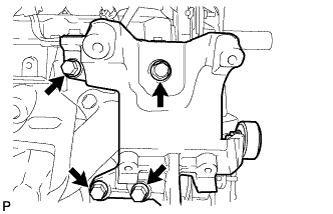
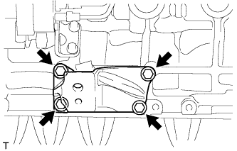
REMOVE NO. 1 COMPRESSOR MOUNTING BRACKET
Remove the 4 bolts and compressor mounting bracket.
3.
REMOVE TIMING BELT
Remove the timing belt (Click here ).
4.
REMOVE INJECTION PUMP ASSEMBLY
Remove the injection pump (Click here ).
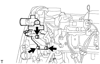
5.
REMOVE WATER OUTLET HOUSING
Remove the 3 bolts, outlet housing and gasket.
6.
REMOVE WATER BY-PASS HOSE UNION
Remove the water by-pass hose union.
7.
REMOVE PUMP BRACKET
Remove the 3 bolts and pump bracket.
8.
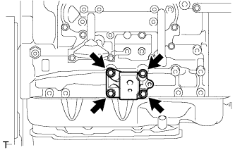
REMOVE NO. 1 FRONT ENGINE MOUNTING BRACKET RH
Remove the 4 bolts and engine mounting bracket.
9.
REMOVE NO. 1 FRONT ENGINE MOUNTING BRACKET LH
Remove the 4 bolts and engine mounting bracket.
10.
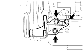
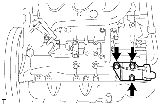
REMOVE NO. 1 GENERATOR BRACKET
Remove the 3 bolts and No. 1 generator bracket.
11.
REMOVE CAMSHAFT TIMING PULLEY
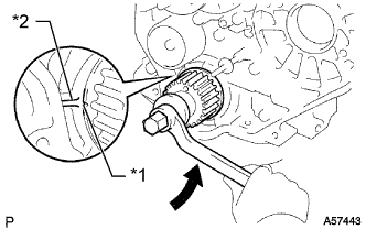
Using the crankshaft pulley bolt, turn the crankshaft 90° counterclockwise and align the timing mark of the crankshaft timing pulley with the protrusion of the timing belt case.
Text in Illustration
Turn
*1
Timing Mark
*2
Protrusion
HINT:
Set the No. 1 cylinder to 90° BTDC/compression to avoid interference with the piston top and valve head.
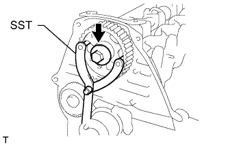
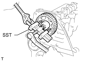
Using SST, loosen the pulley bolt.
SST
09960-10010
(09962-01000, 09963-01000)
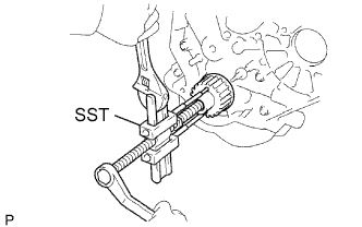
Using SST, separate the timing pulley from the camshaft.
SST
09950-50013
(09951-05010, 09952-05010, 09953-05010, 09954-05021)
Remove the pulley bolt and timing pulley.
Remove the timing pulley woodruff key.
12.
REMOVE NO. 2 TIMING BELT COVER
Remove the 4 bolts and timing belt cover.
13.
REMOVE WATER PUMP ASSEMBLY
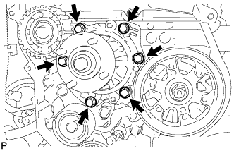
Remove the 6 bolts and tension spring bracket. Remove the water pump and gasket.
14.
REMOVE NO. 1 TIMING BELT IDLER SUB-ASSEMBLY
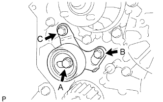
Remove the 2 bolts (A and B).
Loosen the bolt (C), and remove the No. 1 timing belt idler.
15.
REMOVE NO. 2 TIMING BELT IDLER SUB-ASSEMBLY
Remove the bolt, No. 2 timing belt idler and spacer.
16.
REMOVE CRANKSHAFT TIMING PULLEY
Using a screwdriver, remove the crankshaft timing pulley.
SST
09950-50013
(09951-05010, 09952-05010, 09953-05010, 09953-05020, 09954-05010)
HINT:
If the timing pulley cannot be removed by using a screwdriver, remove it with SST.
17.
REMOVE OIL PAN SUB-ASSEMBLY
Remove the 16 bolts and 2 nuts.
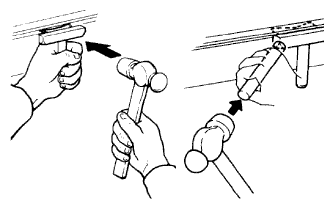
Insert the blade of an oil pan seal cutter between the oil pan and cylinder block, cut off the applied sealer and remove the oil pan.
NOTICE:
Do not use an oil pan seal cutter for the timing belt case side and rear oil seal retainer.
Be careful not to damage the oil pan flange.
18.
REMOVE OIL STRAINER SUB-ASSEMBLY
Remove the 2 bolts, 2 nuts, oil strainer and gasket.
19.
REMOVE TIMING BELT CASE SUB-ASSEMBLY
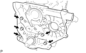
Remove the 5 bolts, timing belt case and gasket.
20.
REMOVE FRONT CRANKSHAFT OIL SEAL
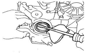
Using a screwdriver, pry out the oil seal.
NOTICE:
Tape the screwdriver tip before use.