2013-2015 Land Cruiser Prado · Service Manual Drivetrain

REMOVAL

Removal / installation · Vehicles built from Aug 2014

Versions by build date: Aug 2013 – Jul 2014 from Aug 2014


1. DISCONNECT CABLE FROM NEGATIVE BATTERY TERMINAL

NOTICE:
  1. After turning the ignition switch off, waiting time may be required before disconnecting the cable from the battery terminal. Therefore, make sure to read the disconnecting the cable from the battery terminal notice before proceeding with work (Click here).
  2. When disconnecting the cable, some systems need to be initialized after the cable is reconnected (Click here).


2. REMOVE NO. 1 ENGINE UNDER COVER SUB-ASSEMBLY
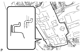
  1. Remove the 4 bolts.

  1. A224743
    Unhook the engine under cover from the vehicle body as shown in the illustration.


3. REMOVE REAR ENGINE UNDER COVER ASSEMBLY
  1. Remove the 4 bolts and rear engine under cover.


4. REMOVE FRONT FENDER APRON SEAL RH
  1. Remove the 5 clips and front fender apron seal.


5. REMOVE FRONT NO. 1 FENDER APRON TO FRAME SEAL RH
  1. Remove the 5 clips and front No. 1 fender apron to frame seal.


6. DRAIN AUTOMATIC TRANSMISSION FLUID
  1. Remove the drain plug and gasket, and drain the ATF.

  1. Install a new gasket and the drain plug.

    Torque:
    20 N*m{ 204 kgf*cm , 15 ft.*lbf }


7. DRAIN ENGINE COOLANT (w/o Air Cooled Transmission Oil Cooler)

CAUTION:
Do not remove the radiator cap while the engine and radiator are still hot. Pressurized, hot engine coolant and steam may be released and cause serious burns.


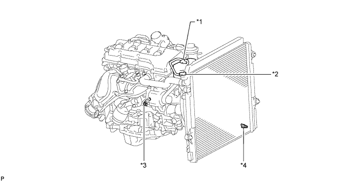
A223311E01
Text in Illustration 
*1
Reservoir Cap
*2
Radiator Cap
*3
Cylinder Block Drain Cock Plug
*4
Radiator Drain Cock Plug

  1. G038197E02
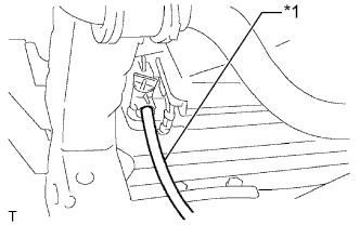
    Install a vinyl hose to the radiator side.
    Text in Illustration 
    *1
    Vinyl Hose

  1. G038198E02
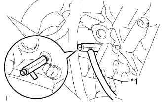
    Install a vinyl hose to the engine side.
    Text in Illustration 
    *1
    Vinyl Hose

  1. Loosen the radiator drain cock plug.

  1. Remove the radiator cap and drain the coolant.

    HINT:
    Collect the coolant in a container and dispose of it according to the regulations in your area.

  1. Loosen the cylinder block drain cock plug and drain the coolant from the engine.


8. REMOVE TRANSFER CASE LOWER PROTECTOR
  1. Remove the 4 bolts and transfer case lower protector.


9. REMOVE FRONT EXHAUST PIPE ASSEMBLY
  1. Remove the front exhaust pipe assembly (Click here).


10. REMOVE FRONT PROPELLER SHAFT ASSEMBLY
  1. Remove the front propeller shaft (Click here).


11. REMOVE PROPELLER SHAFT ASSEMBLY
  1. Remove the propeller shaft (Click here).


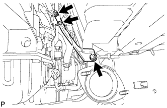
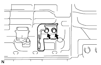
12. REMOVE MANIFOLD STAY

  1. C171485
    Remove the 3 bolts and stay.


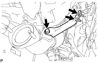
13. REMOVE NO. 2 MANIFOLD STAY

  1. C171486
    Remove the 3 bolts and stay.


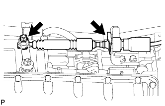
14. DISCONNECT TRANSMISSION CONTROL CABLE ASSEMBLY

  1. C214587
    Remove the nut and clip and disconnect the transmission control cable from the transmission.


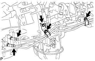
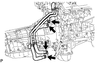
15. DISCONNECT NO. 1 OIL COOLER INLET TUBE AND NO. 1 OIL COOLER OUTLET TUBE (w/ Air Cooled Transmission Oil Cooler)

  1. C218111
    Remove the 2 bolts to open 2 No. 2 flexible hose clamps.

  1. Using a union nut wrench, disconnect the inlet tube and outlet tube from each oil cooler tube union.

  1. Remove the bolt and No. 2 flexible hose clamp from the transmission housing.


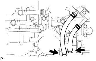
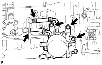
16. REMOVE TRANSMISSION OIL COOLER ASSEMBLY (w/o Air Cooled Transmission Oil Cooler)

  1. C214427
    Disconnect the 2 water by-pass hoses from the transmission oil cooler, and remove the 2 bolts and separate the by-pass pipe from the automatic transmission.

    NOTICE:
    Use a container to catch any coolant which flows out of the water by-pass hoses.

  1. C218112
    Disconnect the No. 2 oil cooler inlet hose and No. 2 oil cooler outlet hose from the transmission oil thermostat.

  1. C218113
    Disconnect the No. 1 oil cooler inlet hose and No. 1 oil cooler outlet hose from each oil cooler tube union.

  1. Remove the 3 bolts and transmission oil cooler with transmission oil thermostat.


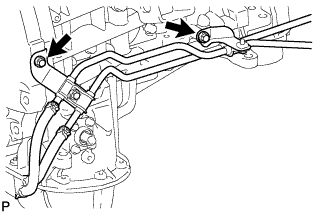
17. DISCONNECT NO. 1 OIL COOLER INLET TUBE AND NO. 1 OIL COOLER OUTLET TUBE (w/o Air Cooled Transmission Oil Cooler)

  1. C218114
    Remove the 2 bolts and disconnect the 2 oil cooler tubes.


18. REMOVE STARTER ASSEMBLY
  1. Remove the starter (Click here).


19. REMOVE DRIVE PLATE AND TORQUE CONVERTER CLUTCH SETTING BOLT

  1. C157016E01
    Remove the flywheel housing side cover.

  1. C157017E01
    Turn the crankshaft to gain access to the 6 bolts and remove each bolt while holding the crankshaft pulley setting bolt with a wrench.


20. SUPPORT AUTOMATIC TRANSMISSION ASSEMBLY

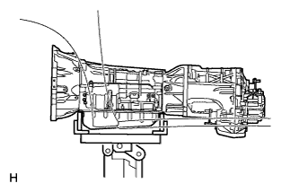
C159641
  1. Support the transmission with a transmission jack. Lift the transmission slightly from the crossmember.


21. REMOVE FRONT SUSPENSION MEMBER BRACKET LH AND RH

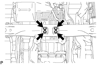
  1. C214435
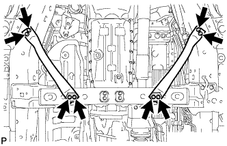
    Remove the 8 bolts, front suspension member bracket LH and RH.


22. REMOVE NO. 3 FRAME CROSSMEMBER SUB-ASSEMBLY

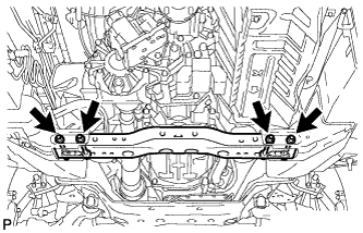
  1. C171489
    Remove the 4 bolts of the rear engine mounting insulator.

  1. C214464
    Remove the 4 nuts, 4 bolts and frame crossmember.


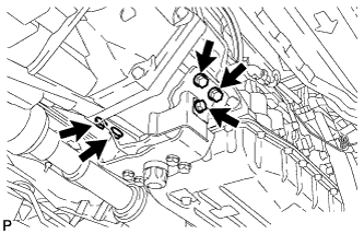
23. REMOVE REAR NO. 1 ENGINE MOUNTING INSULATOR

C214463
  1. Remove the bolt and rear engine mounting heat insulator.

  1. Remove the 4 bolts and rear engine mounting insulator from the transmission.


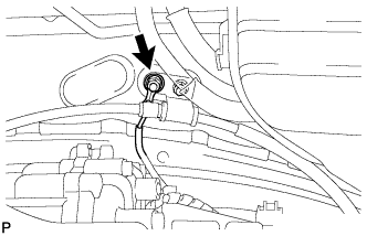
24. DISCONNECT WIRE HARNESS AND CONNECTOR

  1. C214940
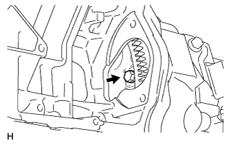
    Remove the nut and disconnect the ground cable.

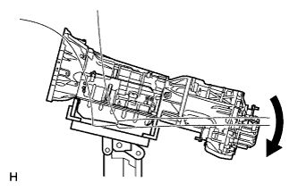
  1. C157274
    Tilt the transmission downward.

    NOTICE:
    Make sure the cooling fan does not contact the fan shroud.

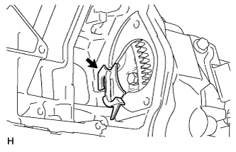
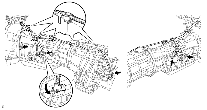
  1. Disconnect the park/neutral position switch connector, transmission wire connector, 2 speed sensor connectors and transfer control side connector.

    HINT:
    Detach the claw, press down the lever, and then disconnect the transmission wire connector.

  1. Detach the 2 connector clamps and 7 harness clamps, and disconnect the wire harness.

    C218115E01


25. DISCONNECT BREATHER PLUG HOSE

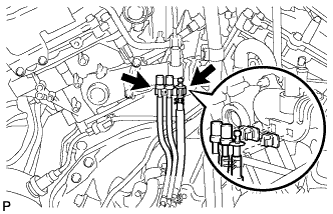
C214459
  1. Disconnect the 3 breather plug hoses from the engine.


26. REMOVE AUTOMATIC TRANSMISSION ASSEMBLY

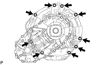
C171497
  1. Remove the 9 bolts and transmission.

    NOTICE:
    Do not use excess force when prying the transmission assembly.


27. REMOVE TRANSFER ASSEMBLY
  1. Remove the transfer (Click here).


28. REMOVE TRANSMISSION CONTROL CABLE BRACKET

  1. C111232
    Remove the 2 bolts and control cable bracket.


29. REMOVE TORQUE CONVERTER CLUTCH ASSEMBLY

30. INSPECT TORQUE CONVERTER CLUTCH ASSEMBLY
  1. Inspect the torque converter clutch (Click here).

← REMOVAL (Aug 2013 – Jul 2014)INSTALLATION (Aug 2013 – Jul 2014) →