2013-2015 Land Cruiser Prado · Service Manual Vehicle Interior

Park / Neutral Position Switch Circuit

Circuit diagnosis · Vehicles built from Aug 2014

Versions by build date: Aug 2013 – Jul 2014 from Aug 2014

DESCRIPTION

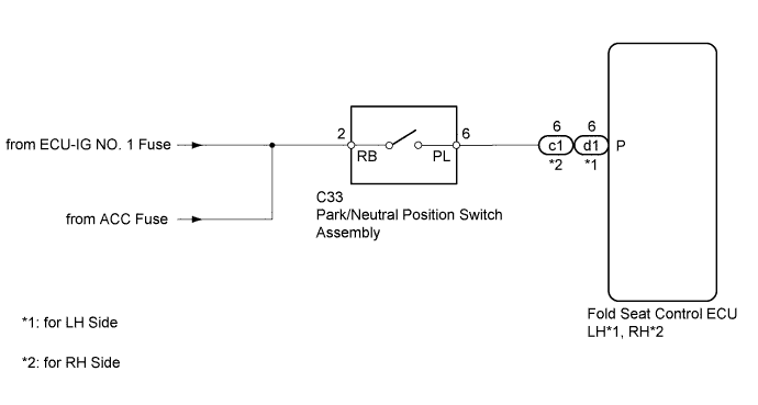
The fold seat control ECU receives signals from the park/neutral position switch and controls the seat folding and return operations. If the shift lever is in any position other than P when the ignition switch is ON, the seat cannot be operated.

WIRING DIAGRAM

B239510E01

INSPECTION PROCEDURE


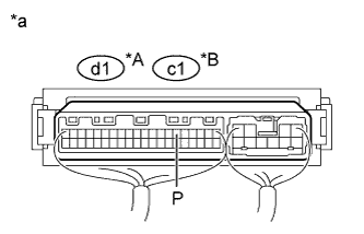
1. CHECK FOLD SEAT CONTROL ECU (PARK/NEUTRAL POSITION SWITCH SIGNAL)

  1. B243481E01
    Remove the fold seat control ECU with its connectors still connected (Click here).

  1. Measure the voltage according to the value(s) in the table below.

    Standard Voltage:
    for LH Side 
    Tester Connection
    Condition
    Specified Condition
    d1-6 (P) - Body ground
    Ignition switch ACC or ON
    Shift lever in P
    11 to 14 V
    Ignition switch ACC or ON
    Shift lever not in P
    Below 1 V
    for RH Side 
    Tester Connection
    Condition
    Specified Condition
    c1-6 (P) - Body ground
    Ignition switch ACC or ON
    Shift lever in P
    11 to 14 V
    Ignition switch ACC or ON
    Shift lever not in P
    Below 1 V

    Text in Illustration 
    *A
    for LH Side
    *B
    for RH Side
    *a
    Component with harness connected
    (Fold Seat Control ECU)


NG
Go to step 2
OK

PROCEED TO NEXT SUSPECTED AREA SHOWN IN PROBLEM SYMPTOMS TABLE (Click here)

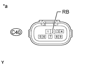
2. CHECK HARNESS AND CONNECTOR (PARK/NEUTRAL POSITION SWITCH - BATTERY)

  1. C197711E31
    Disconnect the C40 switch connector.

  1. Measure the voltage according to the value(s) in the table below.

    Standard Voltage:
    Tester Connection
    Switch Condition
    Specified Condition
    C40-2 (RB) - Body ground
    Ignition switch ACC or ON
    11 to 14 V
    Ignition switch off
    Below 1 V

    Text in Illustration 
    *a
    Front view of wire harness connector
    (to Park/Neutral Position Switch Assembly)


NG
REPAIR OR REPLACE HARNESS OR CONNECTOR
OK


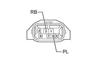
3. INSPECT PARK/NEUTRAL POSITION SWITCH ASSEMBLY

  1. C208647E05
    Disconnect the C40 switch connector.

  1. Measure the resistance according to the value(s) in the table below.

    Standard Resistance:
    Tester Connection
    Condition
    Specified Condition
    2 (RB) - 6 (PL)
    Shift lever in P
    Below 1 Ω
    2 (RB) - 6 (PL)
    Shift lever not in P
    10 kΩ or higher

    Result 
    Result
    Proceed to
    OK
    A
    NG (for A343F Automatic Transmission)
    B
    NG (for A750F Automatic Transmission)
    C


B
REPLACE PARK/NEUTRAL POSITION SWITCH ASSEMBLY (Click here)

C
REPLACE PARK/NEUTRAL POSITION SWITCH ASSEMBLY (Click here)
A


4. CHECK HARNESS AND CONNECTOR (FOLD SEAT CONTROL ECU - PARK/NEUTRAL POSITION SWITCH)
  1. Disconnect the d1*1 or c1*2 ECU connector.

    1. *1: for LH Side
    2. *2: for RH Side

  1. Disconnect the C40 switch connector.

  1. Measure the resistance according to the value(s) in the table below.

    Standard Resistance:
    for LH Side 
    Tester Connection
    Condition
    Specified Condition
    d1-6 (P) - C40-6 (PL)
    Always
    Below 1 Ω
    d1-6 (P) - Body ground
    Always
    10 kΩ or higher
    for RH Side 
    Tester Connection
    Condition
    Specified Condition
    c1-6 (P) - C40-6 (PL)
    Always
    Below 1 Ω
    c1-6 (P) - Body ground
    Always
    10 kΩ or higher


NG
REPAIR OR REPLACE HARNESS OR CONNECTOR
OK

REPLACE FOLD SEAT CONTROL ECU (Click here)


← Park / Neutral Position Switch Circuit (Aug 2013 – Jul 2014)Parking Brake Switch Circuit (Aug 2013 – Jul 2014) →