1KD-FTV STARTING GLOW PLUG INSTALLATION
PROCEDURE

 19850
1.INSTALL GLOW PLUG
- NOTICE:
- ·
Measure the resistance of the glow plug when reinstalling it. If the result is not as specified, replace the glow plug with a new one.
·Replace the glow plug with a new one when it has been dropped or subjected to a physical impact.
·Remove any carbon deposits from the glow plug hole when reinstalling the glow plug.
Clean the glow plug hole.
Wrap tape around a drill bit with a diameter of 4.4 mm (0.173 in.), 118.5 mm (4.665 in.) from its tip.
Insert the drill bit 118.5 mm (4.665 in.) into the glow plug hole (up to the tape) and remove any carbon deposits by turning the drill bit by hand.
Insert a drill bit with a diameter of 4 mm (0.157 in.) into the glow plug hole and remove any carbon deposits from the end of the glow plug hole by turning the drill bit by hand.
Using a 12 mm deep socket wrench, install the glow plug assembly.
- Torque:
- 18 N*m (178 kgf*cm, 13 ft.*lbf)
- NOTICE:
-
Do not use any tools, such as air tools, which are liable to cause an impact to the glow plugs when installing them.
Install the 4 glow plugs.
- Torque:
- 13 N*m (133 kgf*cm, 10 ft.*lbf)
- NOTICE:
-
Do not use any tools, such as air tools, which are liable to cause an impact to the glow plugs when installing them.
17135A
2.INSTALL NO. 1 INTAKE MANIFOLD INSULATOR
19871
3.INSTALL NO. 1 GLOW PLUG CONNECTOR
Temporarily install the No. 1 glow plug connector with the 4 nuts.
Tighten the 4 nuts.
- Torque:
- 2.2 N*m (22 kgf*cm, 19 in.*lbf)
Install the 4 screw grommets.
Connect the wire harness to the No. 1 glow plug connector with the nut.
- Torque:
- 2.6 N*m (27 kgf*cm, 23 in.*lbf)
Install the screw grommet.
4.INSTALL NO. 2 MANIFOLD STAY
Install the No. 2 manifold stay with the bolt.
- Torque:
- 20 N*m (204 kgf*cm, 15 ft.*lbf)
5.INSTALL INTAKE PIPE STAY
17861F
6.INSTALL INTAKE AIR CONNECTOR WITH DIESEL THROTTLE BODY ASSEMBLY (w/o EGR System)
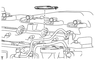
Set a new gasket on the intake manifold.
- NOTICE:
-
Make sure the claw of the gasket face the intake manifold as shown in the illustration.
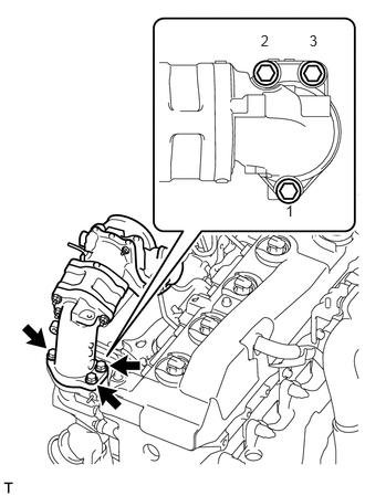
Install the intake air connector with diesel throttle body with the 3 bolts.
- Torque:
- 20 N*m (204 kgf*cm, 15 ft.*lbf)
- NOTICE:
-
Tighten the bolts in the order shown in the illustration.
Connect the throttle position sensor connector.
17871A
7.INSTALL AIR CONNECTOR STAY (w/o EGR System)
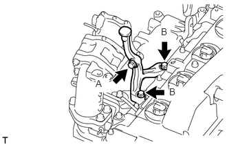
Temporarily install the air connector stay with the 3 bolts.
Tighten the bolt labeled A.
- Torque:
- 20 N*m (204 kgf*cm, 15 ft.*lbf)
Tighten the 2 bolts labeled B.
- Torque:
- 20 N*m (204 kgf*cm, 15 ft.*lbf)
8.CONNECT ENGINE WIRE (w/o EGR System)
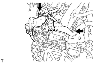
for LHD:
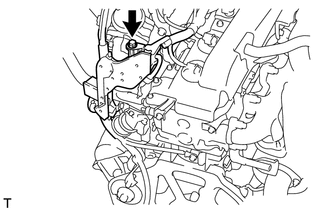
Connect the engine wire with the clamp and install the 2 bolts.
- Torque:
- for bolt A : 13 N*m (131 kgf*cm, 9 ft.*lbf)
- for bolt B : 22 N*m (220 kgf*cm, 16 ft.*lbf)
for RHD:
Connect the engine wire with the bolt.
- Torque:
- 13 N*m (131 kgf*cm, 9 ft.*lbf)
9.INSTALL NO. 1 NO. 2 AND NO. 3 INJECTION PIPE SUB-ASSEMBLY (w/o EGR System)
10.INSTALL THROTTLE BODY BRACKET (w/o EGR System)
Install the throttle body bracket with the 2 bolts.
- Torque:
- 20 N*m (204 kgf*cm, 15 ft.*lbf)
Install the gas filter with gas filter bracket with the bolt.
- Torque:
- 20 N*m (204 kgf*cm, 15 ft.*lbf)
Connect the vacuum hose.
17113E
11.INSTALL NO. 1 INTAKE PIPE (w/o EGR System)
25709E
12.INSTALL NO. 4 VACUUM TRANSMITTING PIPE SUB-ASSEMBLY (w/o EGR System)
87245A
13.INSTALL INLET HEATER WATER HOSE (w/o EGR System)
25800
14.INSTALL ELECTRIC EGR CONTROL VALVE ASSEMBLY (w/ EGR System)
Install the electric EGR control valve (See page Engine / Hybrid System>1KD-FTV (EMISSION CONTROL)>EGR VALVE>INSTALLATION).
15.CONNECT CABLE TO NEGATIVE BATTERY TERMINAL
- NOTICE:
-
When disconnecting the cable, some systems need to be initialized after the cable is reconnected (See page General>INTRODUCTION>REPAIR INSTRUCTION>INITIALIZATION).
16.BLEED AIR FROM FUEL SYSTEM
17.INSPECT FOR FUEL LEAK
18.INSPECT FOR COOLANT LEAK