CRUISE CONTROL CRUISE CONTROL SYSTEM Cruise Control Switch Circuit
DESCRIPTION
The cruise control main switch outputs the signals of the power source for cruise control and the signals of the various operation switches to the ECM.
The ECM performs cruise control in accordance with the signals from the cruise control main switch.
WIRING DIAGRAM
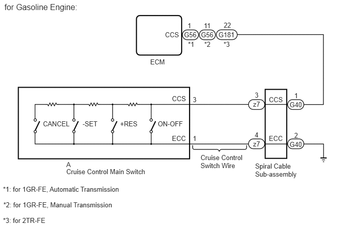
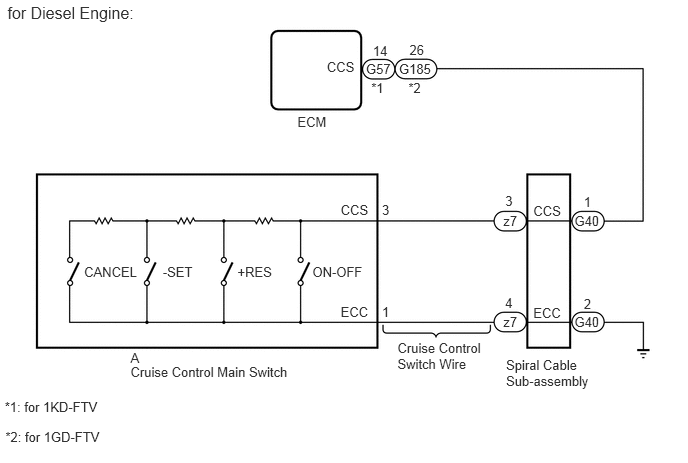
PROCEDURE
Use the Data List to check if the cruise control main switch is functioning properly (See page Engine / Hybrid System>CRUISE CONTROL>CRUISE CONTROL SYSTEM>DATA LIST / ACTIVE TEST).
| Tester Display | Measurement Item/Range | Normal Condition | Diagnostic Note |
|---|---|---|---|
| Main SW M-CPU | Cruise control main switch (Main CPU) / ON or OFF | ON: Cruise control main switch on
OFF: Cruise control main switch off |
- |
| Cancel Switch | CANCEL switch signal / ON or OFF | ON: CANCEL switch on
OFF: CANCEL switch off |
- |
| SET/COAST Switch | -SET switch signal / ON or OFF | ON: -SET switch on
OFF: -SET switch off |
- |
| RES/ACC Switch | +RES switch signal / ON or OFF | ON: +RES switch on
OFF: +RES switch off |
- |
- OK:
On screen, each item changes between ON and OFF according to above chart.
OK
NG
Remove the spiral cable sub-assembly (See page Vehicle Interior>SUPPLEMENTAL RESTRAINT SYSTEMS>SPIRAL CABLE>REMOVAL).
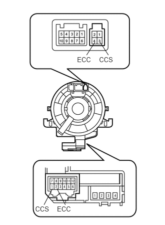
If there are any defects as follows, replace the spiral cable with a new one: scratches, cracks, dents or chips on the connector or spiral cable.
Check the spiral cable.
Set the spiral cable to the center position (See page Vehicle Interior>SUPPLEMENTAL RESTRAINT SYSTEMS>SPIRAL CABLE>INSTALLATION).
Rotate the spiral cable 2.5 times clockwise and measure the resistance according to the value(s) in the table below. Then rotate the spiral cable 5 times counterclockwise and measure the resistance according to the value(s) in the table below.
- NOTICE:
-
As the spiral cable may break, do not rotate the spiral cable more than the specified amount.
- Standard Resistance:
Tester Connection Condition Specified Condition 3 (CCS) - 1 (CCS) Always Below 1 Ω 4 (ECC) - 2 (ECC)
Set the spiral cable to the center position and rotate the spiral cable 2.5 times clockwise. Then, while rotating the spiral cable 5 times counterclockwise, measure the resistance according to the value(s) in the table below.
- Standard Resistance:
Tester Connection Condition Specified Condition 3 (CCS) - 1 (CCS) Always Below 1 Ω 4 (ECC) - 2 (ECC)
OK
NG
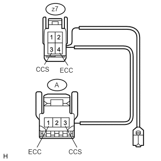
Disconnect the z7 spiral cable connector.
Disconnect the A switch connector.
Measure the resistance according to the value(s) in the table below.
- Standard Resistance:
Tester Connection Condition Specified Condition z7-3 (CCS) - A-3 (CCS) Always Below 2.5 Ω z7-4 (ECC) - A-1 (ECC) z7-3 (CCS) - Body ground Always 1 MΩ or higher z7-4 (ECC) - Body ground
OK
NG
Remove the cruise control main switch (See page Engine / Hybrid System>CRUISE CONTROL>CRUISE CONTROL MAIN SWITCH>REMOVAL).
Inspect the cruise control main switch (See page Engine / Hybrid System>CRUISE CONTROL>CRUISE CONTROL MAIN SWITCH>INSPECTION).
OK
NG
Disconnect the G40 spiral cable connector.
Disconnect the G56*1, G57*2, G181*3 or G185*4 ECM connector.
*1: for 1GR-FE
*2: for 1KD-FTV
*3: for 2TR-FE
*4: for 1GD-FTV
Measure the resistance according to the value(s) in the table below.
- Standard Resistance:
for 1GR-FE, Automatic Transmission Tester Connection Condition Specified Condition G40-1 (CCS) - G56-1 (CCS) Always Below 1 Ω G40-2 (ECC) - Body ground G40-1 (CCS) - Body ground Always 10 kΩ or higher
for 1GR-FE, Manual Transmission Tester Connection Condition Specified Condition G40-1 (CCS) - G56-11 (CCS) Always Below 1 Ω G40-2 (ECC) - Body ground G40-1 (CCS) - Body ground Always 10 kΩ or higher
for 1KD-FTV Tester Connection Condition Specified Condition G40-1 (CCS) - G57-14 (CCS) Always Below 1 Ω G40-2 (ECC) - Body ground G40-1 (CCS) - Body ground Always 10 kΩ or higher
for 2TR-FE Tester Connection Condition Specified Condition G40-1 (CCS) - G181-22 (CCS) Always Below 1 Ω G40-2 (ECC) - Body ground G40-1 (CCS) - Body ground Always 10 kΩ or higher
for 1GD-FTV Tester Connection Condition Specified Condition G40-1 (CCS) - G185-26 (CCS) Always Below 1 Ω G40-2 (ECC) - Body ground G40-1 (CCS) - Body ground Always 10 kΩ or higher
| Result | Proceed to |
|---|---|
| OK (for 1GR-FE) | A |
| OK (for 2TR-FE) | B |
| OK (for 1KD-FTV) | C |
| OK (for 1GD-FTV) | D |
| NG | E |
A
B
C
D
E