DOOR / HATCH FRONT DOOR REASSEMBLY
CAUTION / NOTICE / HINT
- HINT:
- ·
Use the same procedure for RHD and LHD vehicles.
·The procedure listed below is for LHD vehicles.
·Use the same procedure for the RH and LH sides.
·The procedure listed below is for the LH side.
·A bolt without a torque specification is shown in the standard bolt chart (See page General>SPECIFICATIONS>STANDARD BOLT>SPECIFIED TORQUE FOR STANDARD BOLTS).
PROCEDURE

 67001A
1.INSTALL FRONT DOOR PANEL CUSHION
Attach the clip to install a new door panel cushion.
2. REPAIR INSTRUCTION
75976G
3.INSTALL LOWER FRONT DOOR OUTSIDE STRIPE LH
75986F
4.INSTALL FRONT DOOR OUTSIDE STRIPE LH
75922M
5.INSTALL NO. 1 BLACK OUT TAPE LH
75756C
6.INSTALL FRONT DOOR REAR WINDOW FRAME MOULDING LH
75712B
7.INSTALL FRONT DOOR BELT MOULDING LH
67862
8.INSTALL FRONT DOOR WEATHERSTRIP LH
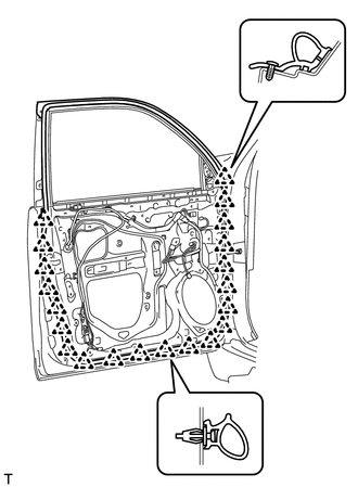
Attach the 21 clips to install a new front door weatherstrip.
68620
9.INSTALL FRONT DOOR CHECK ASSEMBLY LH
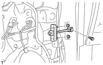
Install the door check to the door panel with the 2 nuts.
- Torque:
- 8.0 N*m (82 kgf*cm, 71 in.*lbf)
Apply adhesive to the threads of the bolt.
- Adhesive:
Toyota Genuine Adhesive 1324, Three Bond 1324 or equivalent
Install the front door check assembly with the bolt.
- Torque:
- 27 N*m (275 kgf*cm, 20 ft.*lbf)
67924
10.INSTALL FRONT DOOR NO. 2 STIFFENER CUSHION
Clean the installation surface.
Using a heat light, heat the installation surface.
- Standard:
Item Temperature Vehicle body 40 to 60°C (104 to 140°F)
- NOTICE:
-
Do not heat the vehicle body excessively.
Remove the double-sided tape from the installation surface.
Wipe off any tape adhesive residue with cleaner.
Install a new door stiffener cushion.
Using a heat light, heat a new front door No. 2 stiffener cushion and the installation surface.
- HINT:
-
When installing the front door No. 2 stiffener cushion, heat the vehicle body and door stiffener cushion using a heat light.
- Standard:
Item Temperature Door stiffener cushion 20 to 30°C (68 to 86°F) Vehicle body 40 to 60°C (104 to 140°F)
- NOTICE:
-
Do not heat the door stiffener cushion and vehicle body excessively.
Remove the peeling paper from the face of the door stiffener cushion.
- HINT:
-
After removing the peeling paper, keep the exposed adhesive free from foreign matter.
Attach the 2 clamps and double-sided tape to install the front door No. 2 stiffener cushion.
- HINT:
-
Press the front door No. 2 stiffener cushion firmly to install it.
Install the 2 bolts.
69312
11.INSTALL FRONT DOOR LOCK OPEN ROD LH
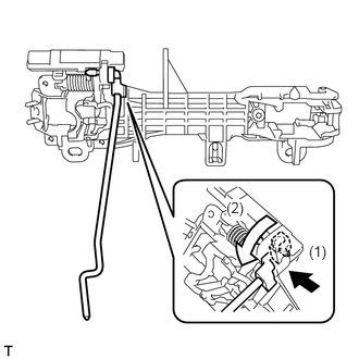
Install the front door lock open rod as indicated by the arrows in the order shown in the illustration.
82152A
12.INSTALL FRONT DOOR NO. 2 WIRE LH (w/ Smart Entry and Start System)
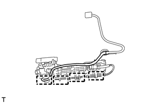
Attach the 4 clamps to install the front door No. 2 wire.
69202A
13.INSTALL FRONT DOOR OUTSIDE HANDLE FRAME SUB-ASSEMBLY LH
Apply MP grease to the sliding parts of the front door outside handle frame sub-assembly.
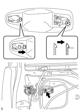
Attach the door handle nut and claw.
Using a T30 "TORX" socket wrench, install the front door outside handle frame sub-assembly with the screw.
- Torque:
- 4.0 N*m (41 kgf*cm, 35 in.*lbf)
w/ Entry and Start System:
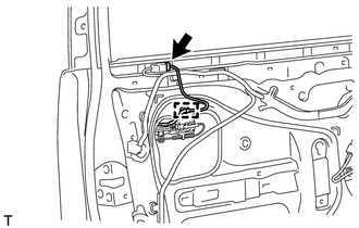
Attach the clamp.
Connect the front door No. 2 wire connector to the front door wire.
69254C
14.INSTALL FRONT DOOR REAR OUTSIDE HANDLE PAD LH
Attach the 2 claws to install the front door rear outside handle pad.
69252
15.INSTALL FRONT DOOR FRONT OUTSIDE HANDLE PAD LH
Attach the 3 claws to install the front door front outside handle pad.
69220
16.INSTALL FRONT DOOR OUTSIDE HANDLE ASSEMBLY LH
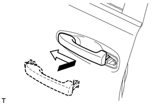
Insert the front end of the front door outside handle assembly into the front door outside handle frame.
Insert the rear end of the front door outside handle assembly into the front door outside handle frame, and then slide the front door outside handle assembly toward the front of the vehicle to install it.
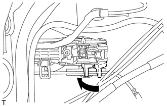
Move the lever in the direction indicated by the arrow in the illustration to lock the door outside handle assembly.
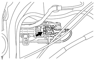
Connect the connector.
Attach the 2 claws.
69760C
17.INSTALL FRONT DOOR INSIDE LOCKING CABLE ASSEMBLY LH
Install the front door inside locking cable assembly.
Attach the 3 claws.
69720B
18.INSTALL FRONT DOOR LOCK REMOTE CONTROL CABLE ASSEMBLY LH
Install the front door lock remote control cable assembly.
69040A
19.INSTALL FRONT DOOR LOCK ASSEMBLY LH
69217E
20.INSTALL FRONT DOOR OUTSIDE HANDLE COVER RH (for Front Passenger Side)
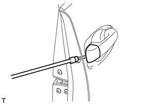
Using a T30 "TORX" socket wrench, install the front door outside handle cover with the screw.
- Torque:
- 4.0 N*m (41 kgf*cm, 35 in.*lbf)
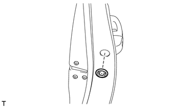
Install the hole plug.
69217F
21.INSTALL FRONT DOOR OUTSIDE HANDLE COVER LH (for Driver Side)
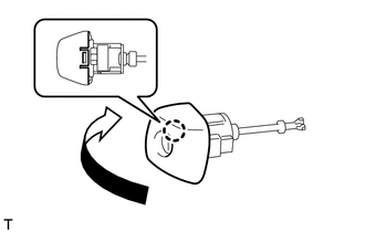
Attach the claw to install the front door outside handle cover to the front door lock cylinder.
22.INSTALL FRONT DOOR OUTSIDE HANDLE COVER WITH LOCK CYLINDER ASSEMBLY (for Driver Side)
Install the front door outside handle cover with lock cylinder assembly.
- HINT:
-
Make sure that the front door lock cylinder rod is inserted into the front door lock assembly.
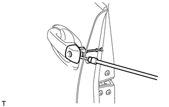
Using a T30 "TORX" socket wrench, install the front door lock cylinder with the screw.
- Torque:
- 4.0 N*m (41 kgf*cm, 35 in.*lbf)
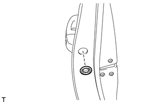
Install the hole plug.
67404F
23.INSTALL FRONT DOOR REAR LOWER FRAME SUB-ASSEMBLY LH
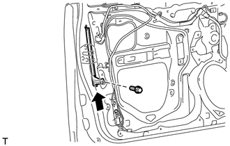
Install the front door rear lower frame sub-assembly with the bolt as shown in the illustration.
68151D
24.INSTALL FRONT DOOR GLASS RUN LH
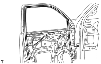
Install the front door glass run.
67664C
25.INSTALL DOOR FRAME GARNISH LH
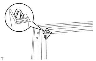
Attach the clip to install a new door frame garnish.
85720C
26.INSTALL FRONT POWER WINDOW REGULATOR MOTOR ASSEMBLY LH
69802
27.INSTALL FRONT DOOR WINDOW REGULATOR SUB-ASSEMBLY LH
Apply MP grease to the sliding parts of the front door window regulator assembly.
Install the temporary bolt to the front door window regulator assembly.
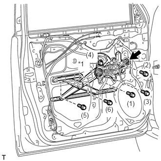
Temporarily install the front door window regulator assembly with the temporary bolt.
| *1 | Temporary Bolt |
Temporarily install the 5 bolts, and then tighten the temporary bolt and 5 bolts.
- Torque:
- 8.0 N*m (82 kgf*cm, 71 in.*lbf)
- HINT:
-
Tighten the bolts in the order shown in the illustration.
Connect the connector.
68102
28.INSTALL FRONT DOOR GLASS SUB-ASSEMBLY LH
Connect the cable to the negative (-) battery terminal.
Connect the power window regulator master switch assembly and move the front door glass sub-assembly so that the door glass bolt installation locations can be seen.
Disconnect the cable from the negative (-) battery terminal and power window regulator master switch assembly.
- CAUTION:
-
Wait at least 90 seconds after disconnecting the cable from the negative (-) battery terminal to disable the SRS system (See page General>INTRODUCTION>REPAIR INSTRUCTION>INITIALIZATION).
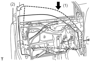
Insert the front door glass sub-assembly into the front door panel along the front door glass run as indicated by the arrows in the order shown in the illustration.
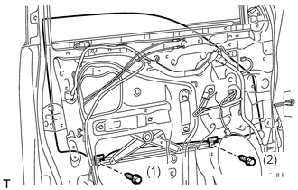
Install the front door glass sub-assembly with the 2 bolts.
- Torque:
- 5.5 N*m (56 kgf*cm, 49 in.*lbf)
- HINT:
-
Tighten the bolts in the order shown in the illustration.
87940
29.INSTALL OUTER REAR VIEW MIRROR ASSEMBLY LH
67832
30.INSTALL FRONT DOOR SERVICE HOLE COVER LH
Apply new butyl tape to the front door panel.
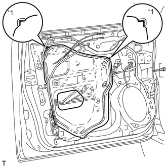
Pass the front door lock remote control cable assembly and front door inside locking cable assembly through a new front door service hole cover.
| *1 | Reference Point |
Attach the front door service hole cover using the reference points on the front door panel.
- NOTICE:
- ·
There should be no wrinkles or folds after attaching the service hole cover.
·After attaching the service hole cover, check the seal quality.
- NOTICE:
-
Securely install the front door service hole cover preventing wrinkles and air bubbles.
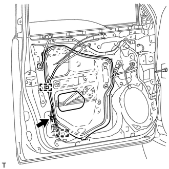
Attach the 2 clamps.
Install the bolt to the front door wire.
89860A
31.INSTALL SIDE AIRBAG SENSOR ASSEMBLY LH
86160
32.INSTALL FRONT NO. 1 SPEAKER ASSEMBLY
84927
33.INSTALL SEAT MEMORY SWITCH (w/ Seat Position Memory System)
69206B
34.INSTALL FRONT DOOR INSIDE HANDLE SUB-ASSEMBLY LH
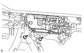
Attach the guide and 2 claws to install the front door inside handle sub-assembly to the front door trim board sub-assembly.
Install the 2 screws.
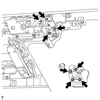
Install the 8 screws to the door assist grip assembly LH.
84810
35.INSTALL POWER WINDOW REGULATOR SWITCH ASSEMBLY (for Front Passenger Side)
84040
36.INSTALL MULTIPLEX NETWORK MASTER SWITCH ASSEMBLY (for Driver Side)
Install the multiplex network master switch assembly with the 3 screws.
81080E
37.INSTALL FRONT DOOR INSIDE HANDLE ILLUMINATION LIGHT ASSEMBLY LH
81081A
38.INSTALL NO. 2 INTERIOR ILLUMINATION LIGHT SUB-ASSEMBLY
81910A
39.INSTALL FRONT REFLEX REFLECTOR ASSEMBLY
Attach the 2 claws to install the front reflex reflector assembly.
68172A
40.INSTALL FRONT DOOR INNER GLASS WEATHERSTRIP LH
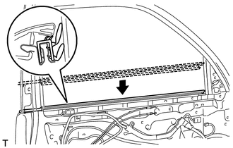
Install the front door inner glass weatherstrip.
67602
41.INSTALL FRONT DOOR TRIM BOARD SUB-ASSEMBLY LH
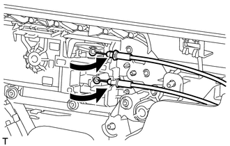
Connect the front door lock remote control cable assembly and front door inside locking cable assembly.
Connect 2 connectors.
w/ Seat Position Memory System:
Connect the connectors.
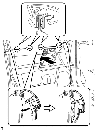
Attach the front door trim board sub-assembly by attaching the 4 claws of the front door inner glass weatherstrip as shown in the illustration.
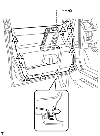
Attach the 12 clips and front door trim board retainer to install the front door trim board sub-assembly.
Install the 3 screws.
74611C
42.INSTALL ASSIST GRIP COVER LH
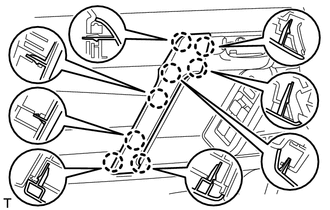
Attach the 8 claws to install the assist grip cover.
69298A
43.INSTALL NO. 2 DOOR INSIDE HANDLE BEZEL LH
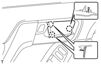
Attach the 3 claws to install the inside handle bezel.
67492A
44.INSTALL FRONT DOOR LOWER FRAME BRACKET GARNISH LH
Attach the 2 claws to install the front door lower frame bracket garnish.
45.CONNECT CABLE TO NEGATIVE BATTERY TERMINAL
- NOTICE:
-
When disconnecting the cable, some systems need to be initialized after the cable is reconnected (See page General>INTRODUCTION>REPAIR INSTRUCTION>INITIALIZATION).
46.INITIALIZE POWER WINDOW CONTROL SYSTEM
Initialize the power window (See page Vehicle Exterior>WINDOW / GLASS>POWER WINDOW CONTROL SYSTEM>INITIALIZATION).
47.CHECK SRS WARNING LIGHT
Check the SRS warning light (See page Vehicle Interior>SUPPLEMENTAL RESTRAINT SYSTEMS>AIRBAG SYSTEM>DIAGNOSIS SYSTEM).
86790C
48.ADJUST SIDE TELEVISION CAMERA ASSEMBLY (w/ Side Monitor System)